Beretta926
- 9
- 1
Ok y'all, thanks for the assist.
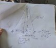
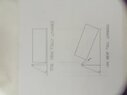
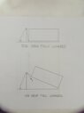
I am in the middle of building a dump trailer, mechanical lift with winch or a mounted lift points. For stability side to side I have elected to make the standing pole an A frame design. I need to know the best width at the base to use for load (comparing to a straight pole of equal size.
Let's say 2 poles standing straight have a max lift of 1000lb. This same 2 poles will have a max lift of ( ? ) if the base is 18" wide vs 26" wide. The lift points on the poles is at 96" (poles are 98", but I need metal remaining for bolts and welds)
So, how much lift strength do I lose to the A frame at those 2 widths. Thanks so much