stateissuedrx78
- 6
- 6
- Homework Statement
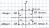
- A short vertical electric dipole of moment Iℓ (pointed in z direction) is placed at (a,0,a) [the xz plane, y-axis is in and out of page] and there are two infinitely long PECs, one located on the x-axis and one located at the z-axis. Use image theory to remove the two PEC planes and replace their effects with properly positioned and oriented three additional image dipoles. Calculate the vector 𝑵(𝜃,𝜙) due to the four dipoles (source + three images).
- Relevant Equations
- attached inline.
PREFACE: My first real post so please bear with me and my notation and layout. I tried to make it as easy on the eyes as possible...
While I am fairly confident of my process thus far, I feel I may be straying from the answer a bit towards the end.
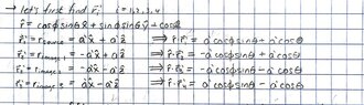
Considering the short vertical electric dipole in the +z direction, the images should be the following (I have also attached my own drawing):
source: located at (a,0,a) - oriented in the +z direction with moment Iℓ
image 1: located at (-a,0,a) - oriented in the -z direction i.e. -Iℓ moment (tangential components of E should be zero across the PEC plane)
image 2: located at (-a,0,-a) - oriented in the -z direction i.e. -Iℓ moment (normal component of E should reinforce image 1)
image 3: located at (a,0,-a) - oriented in the +z direction i.e. +Iℓ moment (normal component of E over PEC should reinforce the source)
.jpg")
Now, for vector N(𝜃,𝜙):
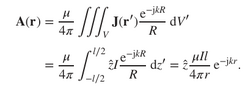
- In the textbook I am using, I found that the magnetic vector potential of an infinitesimal dipole (taken from "short" dipole as stated in the question) oriented the exact same is as given below:

The textbook also states that N and A have the following relationship

with N(𝜃,𝜙) given as

where r'cosΨ = r_hat*r'. where r_hat is just the r unit vector in cartesian form and r' is the source/image distance vector.
My logic is that N(𝜃,𝜙) for the source dipole would simply be Iℓ*exp(jkr_hat*r') in which the total N(𝜃,𝜙) would just be
N(𝜃,𝜙) = N(𝜃,𝜙)_source+N(𝜃,𝜙)_image1+N(𝜃,𝜙)_image2+N(𝜃,𝜙)_image3
or more explicitly as written below (sorry for the sloppy writing):

My next thought was to simply integrate these N's over the surface element dS=dxdz (or dx'dz' to be pedantic). I have not passed this point as the integration seems a bit brutal to tackle without some possible advise on the work so far. Thanks in advance!
While I am fairly confident of my process thus far, I feel I may be straying from the answer a bit towards the end.
Considering the short vertical electric dipole in the +z direction, the images should be the following (I have also attached my own drawing):
source: located at (a,0,a) - oriented in the +z direction with moment Iℓ
image 1: located at (-a,0,a) - oriented in the -z direction i.e. -Iℓ moment (tangential components of E should be zero across the PEC plane)
image 2: located at (-a,0,-a) - oriented in the -z direction i.e. -Iℓ moment (normal component of E should reinforce image 1)
image 3: located at (a,0,-a) - oriented in the +z direction i.e. +Iℓ moment (normal component of E over PEC should reinforce the source)
Now, for vector N(𝜃,𝜙):
- In the textbook I am using, I found that the magnetic vector potential of an infinitesimal dipole (taken from "short" dipole as stated in the question) oriented the exact same is as given below:
The textbook also states that N and A have the following relationship
with N(𝜃,𝜙) given as
where r'cosΨ = r_hat*r'. where r_hat is just the r unit vector in cartesian form and r' is the source/image distance vector.
My logic is that N(𝜃,𝜙) for the source dipole would simply be Iℓ*exp(jkr_hat*r') in which the total N(𝜃,𝜙) would just be
N(𝜃,𝜙) = N(𝜃,𝜙)_source+N(𝜃,𝜙)_image1+N(𝜃,𝜙)_image2+N(𝜃,𝜙)_image3
or more explicitly as written below (sorry for the sloppy writing):
My next thought was to simply integrate these N's over the surface element dS=dxdz (or dx'dz' to be pedantic). I have not passed this point as the integration seems a bit brutal to tackle without some possible advise on the work so far. Thanks in advance!
Attachments
Last edited by a moderator:
