Martin Harris
- 102
- 6
- Homework Statement
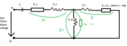
- Given the 3-phased induction machine working as a motor in AC, please see the following diagram attached below, and its parameters.
- Relevant Equations
- Kirchoff's Law
Ohm's Law
Given the following input parameters:
Please note that everything that has an underline below is treated as a phasor.
Following the main s (stator) branch, the m (magnetizing) and r (rotor) sub-branches are in parallel as they can be seen in the attached diagram.
a) (stator current) = ?
$$\underline {Is} =? $$
$$\underline {Is} = \frac {Vsl/sqrt(3)} {z_ab} (Eq1)$$
$$z_{ab} = z_s + z_{parallel} (Eq2)$$
$$z_s = R_s+x_s = (1.4 + 0.6283i) Ω (Eq3)$$
According to Microsoft Math Solver:
$$z_{parallel} = \frac {zm*zr} {zm+zr} =0.5389+3.0254i (Eq4)$$
Substituting Eq3 and Eq4 into Eq2, yields:
$$z_{ab} =(1.9389+3.6537i ) Ω $$
Hence substituting z_ab and Vsl/sqrt(3) into Eq1
$$\underline {Is} =\frac {380/sqrt(3)} {(1.9389+3.6537i ) Ω} $$
$$\underline {Is} =(24.8634−46.8523i) A $$
$$ I_s =53.04080 A $$
b) φ =? (angle)
$$φ = arctan \frac {46.8523} {24.8634} $$
$$φ = 62.04 degrees $$
C) rotor current = ? magnetizing current =?
$$\underline {Ir} = \frac {\underline {Vparallel}} {z_{r}/s} (Eq5)$$
$$\underline {Vparallel} =\underline {Is}*z_{parallel} $$
$$\underline {Vparallel} =(24.8634−46.8523i) A * (0.5389+3.0254i)Ω$$
$$\underline {Vparallel} =155.1458+49.9730i$$
$$V_{parallel} = 162.9954 V $$
Substituting back into Eq5 yields:
$$\underline {Ir} = \frac {155.1458+49.9730i} {17.5 + 0.6283i }$$
$$\underline {Ir} = 8.95645348+2.53403773i$$
$$I_r = 9.3079 A $$
$$\underline {Im} = \frac {\underline {Vparallel}} {z_{m}} (Eq6)$$
$$\underline {Im} = \frac {155.1458+49.9730i} {3.1415i} $$
$$\underline {Im} = 15.9073−49.3858i $$
$$I_r = 51.8844 A $$
d) Stator Power = ?
$$\underline {P_s} = 3* \frac {U_{s}} {sqrt(3)} * I_{s}* cos (φ) $$
$$\underline {P_s} = 3* \frac {380V} {sqrt(3)} *53.04080 *cos (62.04 degrees)$$
$$\underline {P_s} = 16367.8966 W$$
e) Joule stator loss = ? Joule rotor loss = ?
$$L_{js} = 3*R_s* I_s^2 $$
$$L_{js} = 3*1.4 Ω* 53.04080^2 A^2 $$
$$L_{js} = 11815.9711 W $$
$$L_{jr} = 3*R_r* I_r^2 $$
$$L_{jr} = 3*0.7 Ω* 9.3079^2 A^2 $$
$$L_{jr} = 181.9377 W $$
$$L_{mech} = (1.5/100) * P_s = 24.5684 W $$
$$L_{ventilation} = (1/100) * P_s = 16.3789 W $$
f) Electromagnetic Power = ? Mechanical Power =? Assuming negligible L_Fe (Iron losses ~= 0)
$$P_{elm} = P_s - L_{js} = 16367.8966 W - 11815.9711 W $$
$$P_{elm} = 4551.9255 W $$
$$P_{mech} = P_{elm} - L_{jr} = P_{elm} * (1-s) $$
$$P_{mech} = 4551.9255 W -181.9377 W$$
$$P_{mech} = 4369.9878 W $$
g)Electromagnetic torque =? Shaft torque = ?
$$M_{electromagnetic} = \frac {P_{elm}} {Ω_s} $$
$$Ω_s = \frac {2*π*f} {p} = 104.7197 rad/s $$
$$M_{electromagnetic} = \frac {4551.9255 W} {104.7197 rad/s } $$
$$M_{electromagnetic} = 43.4677 Nm$$
$$M_{shaft} = \frac {P_{mech}} {Ω} $$
$$Ω = Ω_s*(1-s) = 100.5309 rad/s $$
$$M_{shaft} = \frac {4369.9878 W} {100.5309 rad/s } $$
$$M_{shaft} = 43.4691Nm$$
I think I am doing something wrong because Kirchoff's Law, doesen't seem to apply such that the the sum of the currents sub-branches Im+Ir > Is (main current).
Was expecting Is (main stator current) = Im+Ir (as the 2 sub-branches run in parallel)
Furthermore the Joule Stator Loss seems to be enormous Ljs =11.81 kW given that the stator Power was calculated as Ps =16.367 kW.
For sure I did something wrong, and I still didn't realize it, and that's why I need your help. I would be more than grateful if someone could check my calculations. Many thanks!
| Parameter | Value |
| Rs (Resistance through stator) | 1.4 Ω |
| Rr (Resistance through stator) | 0.7 Ω |
| Ls (stator inductance) = Lr (rotor inductance) | 0.002 H |
| xs = xr = 2*π*f*Ls | 0.6283i Ω |
| Lm(magnetic inductance) | 0.01 H |
| xm = 2*π*f*Lm | 3.1415iΩ |
| f (frequency) | 50 Hz |
| p (number of pairs of poles) | 3 |
| s (slip) | 0.04 |
| Vsl (Stator line voltage) - star configuration ; Vsp(Stator phase voltage) | 380 V ; 220V |
| zs = Rs +xs | (1.4 + 0.6283i)Ω |
| zm = xm because Rw = 0 (please see diagram attached below) | 3.1415iΩ |
| zr= Rr/s +xr | (17.5 + 0.6283i)Ω |
Please note that everything that has an underline below is treated as a phasor.
Following the main s (stator) branch, the m (magnetizing) and r (rotor) sub-branches are in parallel as they can be seen in the attached diagram.
a) (stator current) = ?
$$\underline {Is} =? $$
$$\underline {Is} = \frac {Vsl/sqrt(3)} {z_ab} (Eq1)$$
$$z_{ab} = z_s + z_{parallel} (Eq2)$$
$$z_s = R_s+x_s = (1.4 + 0.6283i) Ω (Eq3)$$
According to Microsoft Math Solver:
$$z_{parallel} = \frac {zm*zr} {zm+zr} =0.5389+3.0254i (Eq4)$$
Substituting Eq3 and Eq4 into Eq2, yields:
$$z_{ab} =(1.9389+3.6537i ) Ω $$
Hence substituting z_ab and Vsl/sqrt(3) into Eq1
$$\underline {Is} =\frac {380/sqrt(3)} {(1.9389+3.6537i ) Ω} $$
$$\underline {Is} =(24.8634−46.8523i) A $$
$$ I_s =53.04080 A $$
b) φ =? (angle)
$$φ = arctan \frac {46.8523} {24.8634} $$
$$φ = 62.04 degrees $$
C) rotor current = ? magnetizing current =?
$$\underline {Ir} = \frac {\underline {Vparallel}} {z_{r}/s} (Eq5)$$
$$\underline {Vparallel} =\underline {Is}*z_{parallel} $$
$$\underline {Vparallel} =(24.8634−46.8523i) A * (0.5389+3.0254i)Ω$$
$$\underline {Vparallel} =155.1458+49.9730i$$
$$V_{parallel} = 162.9954 V $$
Substituting back into Eq5 yields:
$$\underline {Ir} = \frac {155.1458+49.9730i} {17.5 + 0.6283i }$$
$$\underline {Ir} = 8.95645348+2.53403773i$$
$$I_r = 9.3079 A $$
$$\underline {Im} = \frac {\underline {Vparallel}} {z_{m}} (Eq6)$$
$$\underline {Im} = \frac {155.1458+49.9730i} {3.1415i} $$
$$\underline {Im} = 15.9073−49.3858i $$
$$I_r = 51.8844 A $$
d) Stator Power = ?
$$\underline {P_s} = 3* \frac {U_{s}} {sqrt(3)} * I_{s}* cos (φ) $$
$$\underline {P_s} = 3* \frac {380V} {sqrt(3)} *53.04080 *cos (62.04 degrees)$$
$$\underline {P_s} = 16367.8966 W$$
e) Joule stator loss = ? Joule rotor loss = ?
$$L_{js} = 3*R_s* I_s^2 $$
$$L_{js} = 3*1.4 Ω* 53.04080^2 A^2 $$
$$L_{js} = 11815.9711 W $$
$$L_{jr} = 3*R_r* I_r^2 $$
$$L_{jr} = 3*0.7 Ω* 9.3079^2 A^2 $$
$$L_{jr} = 181.9377 W $$
$$L_{mech} = (1.5/100) * P_s = 24.5684 W $$
$$L_{ventilation} = (1/100) * P_s = 16.3789 W $$
f) Electromagnetic Power = ? Mechanical Power =? Assuming negligible L_Fe (Iron losses ~= 0)
$$P_{elm} = P_s - L_{js} = 16367.8966 W - 11815.9711 W $$
$$P_{elm} = 4551.9255 W $$
$$P_{mech} = P_{elm} - L_{jr} = P_{elm} * (1-s) $$
$$P_{mech} = 4551.9255 W -181.9377 W$$
$$P_{mech} = 4369.9878 W $$
g)Electromagnetic torque =? Shaft torque = ?
$$M_{electromagnetic} = \frac {P_{elm}} {Ω_s} $$
$$Ω_s = \frac {2*π*f} {p} = 104.7197 rad/s $$
$$M_{electromagnetic} = \frac {4551.9255 W} {104.7197 rad/s } $$
$$M_{electromagnetic} = 43.4677 Nm$$
$$M_{shaft} = \frac {P_{mech}} {Ω} $$
$$Ω = Ω_s*(1-s) = 100.5309 rad/s $$
$$M_{shaft} = \frac {4369.9878 W} {100.5309 rad/s } $$
$$M_{shaft} = 43.4691Nm$$
I think I am doing something wrong because Kirchoff's Law, doesen't seem to apply such that the the sum of the currents sub-branches Im+Ir > Is (main current).
Was expecting Is (main stator current) = Im+Ir (as the 2 sub-branches run in parallel)
Furthermore the Joule Stator Loss seems to be enormous Ljs =11.81 kW given that the stator Power was calculated as Ps =16.367 kW.
For sure I did something wrong, and I still didn't realize it, and that's why I need your help. I would be more than grateful if someone could check my calculations. Many thanks!
Attachments
Last edited: