Inductive heating and eddy currents
- Level: Undergrad
- Thread starter MagneticMagic
- Start date
-
- Tags
- Currents Eddy currents Heating
Join the discussion
Registration is free. Start your own thread to ask a follow-up.
60 replies · 9K views
Physics news on Phys.org
MagneticMagic
- 25
- 2
3-4usec is their fall time, slightly slower rise time. Since the two coils are driven 180 out of phase 50% PWM and the "off" time per cycle is ~3-4usec, the B field is "always on". In other words, the B field will very abruptly switch poles very very fast, only takes ~6usec to flip. In a LC tank the flipping of B field is way more gradual per cycle, sine wave gradual. Time wise, with 1kHz drive, full "on" time for each coil per cycle is 1ms/2 - 4usec. So in other words, "always on".artis said:How could the poles not flip at frequency? How can the B field be max at "any given time" if you use switches to switch the current through coils ?
What do you think happens to a DC current as it is being switched through a inductance?
Last edited:
MagneticMagic
- 25
- 2
So are you talking about dB/dt ?artis said:change the B field and as it changes a circular current is induced on the surface of the metal as the B field tries to enter the metal. The moment the B field becomes static aka doesn't change anymore no more currents are induced.
In AC analysis the B field simply flip flops at some frequency, yet depending on the wave used dB/dt can be very very different. Sine wave is "slow", square wave is "fast". Frequency alone of the B poles flipping is not the whole story.
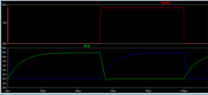
dB/dt has profound effect on eddy current heating. In sine you have some "avg" (rms) B field over 1/2 cycle, because the B field grows and shrinks to the beat of sine. Let's assume Bmax = 10, so rms would be 0.707, in 1kHz (per half cycle) you get 0.707/0.5ms. Take that to DC PWM where I can switch on/off from Bmax (10) in usec. dB/dt is many magnitudes greater with PWM.
Here's 10kHz. The upper is the PWM drive source, the lower shows the two coils. dB/dt is magnitudes higher than sine wave. Yeah, on is a bit slower than 4usec, darn silicon.
Attachments
Last edited:
artis
- 1,479
- 977
So explain in your own words then , what is the benefit in this?MagneticMagic said:the B field is "always on". In other words, the B field will very abruptly switch poles very very fast, only takes ~6usec to flip. In a LC tank the flipping of B field is way more gradual per cycle, sine wave gradual.
Do you know that a square wave actually has multiple sine wave components/harmonics in it , you will get the combined effect of if you just used a higher sine frequency, trying to "square" everything will also add more heat to the work coil itself.
And yes FET's work in on/off modes naturally but if you will use a sufficiently large coil/inductance your real waveform within the coil will approximate sine anyway, that's just natural you can't escape it.
You are going the opposite way, instead of having a field that constantly varies (yes with slower rises and falls) you want to have a field that quickly jumps up and down but stays static inbetween, if you actually look at the waveform graph you should notice that most of the time within a square wave is spent either at max voltage or no voltage while in sine almost all time is spent in a varying voltage mode.
Whenever the voltage reaches a steady level you essentially have steady current passing through the coil, a steady current does not produce a changing magnetic field so a steady current through the work coil is just wasted current as it does not accomplish any goal.
In induction heating you want to just constantly shuffle a B field back and forth and make it penetrate further into the target metal in the least amount of time so you would look for the most efficient way to do that which consumes least energy in the process of doing so. Resonance here accomplishes just that.
But again as I said maybe I'm dead wrong so you are free to explain and prove your method is better than the ones used by most
Science Advisor
Homework Helper
- 6,962
- 6,042
Worse! It then causes ohmic heating in the copper to no benefit.artis said:Whenever the voltage reaches a steady level you essentially have steady current passing through the coil, a steady current does not produce a changing magnetic field so a steady current through the work coil is just wasted current as it does not accomplish any goal.
MagneticMagic
- 25
- 2
AC single coil has constant ohmic heating, and so does two coils PWM 50%.hutchphd said:Worse! It then causes ohmic heating in the copper to no benefit.
In PWM one coil is exactly the same as single AC coil. Hence, not heating any coil more than the single AC coil.
In PWM 50%, the total J wasted from wire ohms is 2x that of AC single coil. Yes, a pitfall using 50% PWM. But duly noted, the two coils in PWM drive will not heat their wire any more than the single AC coil.
But, always a but in there. That's only if it's driven balanced 50% PWM. I can easily change drive down to 25% PWM per coil, thereby less wasted J, and at 25% I am back to same wasted J as the single AC coil.
MagneticMagic
- 25
- 2
Please define "back and forth".artis said:In induction heating you want to just constantly shuffle a B field back and forth
In both models the B field poles flip-flop at some frequency.
In both models dB/dt between zero B and Bmax happens.
The big diff is, in sine wave drive the dB/dt between zero B and Bmax, and Bmax down to zero B, happens much much slower.
So help me understand "back and forth".
artis
- 1,479
- 977
@MagneticMagic take no offense but you seem to be one of those people that come ask for advice but then already seem to have an answer and basically just asked the advice out of curiosity?
We told you why your method is less efficient than the one we proposed , explained the "pluses and minuses".
Now if you wish to still do it your way that is fine but then what's the point of asking?
When I said "back and forth" I just meant a B field that constantly changes in strength and flips polarity.
I suggest you try both methods , your as well as the more conventional I think you should see a difference in how fast the heating happens as well as power consumed.
Also remember that heating will be more even if the metal to be heated is within the coil not outside of it, that is simply due to B field divergence outside of coil especially if you place two coils with same polarity back to back, the field will be deflected a lot and here will be no field in the middle only at the very sides, so your not just wasting current your wasting field.
We told you why your method is less efficient than the one we proposed , explained the "pluses and minuses".
Now if you wish to still do it your way that is fine but then what's the point of asking?
When I said "back and forth" I just meant a B field that constantly changes in strength and flips polarity.
I suggest you try both methods , your as well as the more conventional I think you should see a difference in how fast the heating happens as well as power consumed.
Also remember that heating will be more even if the metal to be heated is within the coil not outside of it, that is simply due to B field divergence outside of coil especially if you place two coils with same polarity back to back, the field will be deflected a lot and here will be no field in the middle only at the very sides, so your not just wasting current your wasting field.
Science Advisor
2025 Award
- 17,270
- 10,732
If the scheme had been described from the start as a push-pull driver then it would have been more obvious what was meant by the misleading “50% PWM”.artis said:... especially if you place two coils with same polarity back to back, the field will be deflected a lot and here will be no field in the middle only at the very sides, ...
Many in this thread are convinced that the coils are driven opposed in polarity, at the same time, when the coils are in fact powered alternately, so the net field through the magnetic core really is alternating and there is no cancellation, just the reversals of alternation.
artis
- 1,479
- 977
Right , completely forgot about this one, still in this approach the OP is effectively only heating one end of the metal at a time , he could connect the coils in series and then the whole of the metal would be heated at once irrespective of his waveform but for some reason that is not an option according to OP.Baluncore said:If the scheme had been described from the start as a push-pull driver then it would have been more obvious what was meant by the misleading “50% PWM”.
Many in this thread are convinced that the coils are driven opposed in polarity, at the same time, when the coils are in fact powered alternately, so the net field through the magnetic core really is alternating and there is no cancellation, just the reversals of alternation.
MagneticMagic
- 25
- 2
See pic in post #25.artis said:Right , completely forgot about this one, still in this approach the OP is effectively only heating one end of the metal at a time , he could connect the coils in series and then the whole of the metal would be heated at once irrespective of his waveform but for some reason that is not an option according to OP.
Why would I have two coils if I was going to connect them in series NS-NS? I would just wind one coil, no?
Heating one end of the metal? The B field passes through the object. The time to heat object is not in this discussion, having to heat super fast (relatively speaking) is not a factor in my project.
And using adjective words, yes, it's a push-pull design using PWM 50% drive. I can adjust the PWM to get various push-pull characteristics, but 50% drive is easier to do in silicon.
Not just alternately, but also in opposite direction magnetically. I made it clear numerous times that both coils were not 'on' at the same time. So with all due respect to all, not sure if folks are reading the posts, or understanding them.Many in this thread are convinced that the coils are driven opposed in polarity, at the same time, when the coils are in fact powered alternately, so the net field through the magnetic core really is alternating and there is no cancellation, just the reversals of alternation.
1st thing is, AC means "alternating current", has no hard ties to voltage.
Lenz laws also tell us the eddy current flips 180deg between +dB/dt and -dB/dt (rise of B field to fall of B field). In other words, in AC, eddy flips 180deg during every 1/2 cycle of AC, or flips twice during every 1 cycle of AC. In DC drive with just one coil, eddy only flips once per cycle. So yes, AC (alternating current = alternating B field, per 1 cycle of drive) = more eddy heating, hence when driving with just DC it's best to create alternating current, which can be done a few ways using silicon.
And to be clear, I could do the basic LC tank with one coil, but my drive circuitry allows for "instant" control of frequency and B field strength, making the drive section way more flexible than an LC tank setup.
And yes, I already understand there's Pros & Cons to everything. More flexibility for less efficiency sometimes makes the solution more attractive. I understand the efficiencies.
Last edited:
artis
- 1,479
- 977
Matter of choiceMagneticMagic said:Why would I have two coils if I was going to connect them in series NS-NS? I would just wind one coil, no?
No, a changing B field never passes through a solid metal, that is why the eddy currents form in the first place, they resist the B field that tries to enter the material by creating their own B field which is of opposite polarity , the overall effect is that of a decrease in the primary B field strength. This is induction so think of it like a transformer analogy, your piece of metal is the secondary, just short circuited and a weird shape that it.MagneticMagic said:The B field passes through the object.
As I said having the B field from just one side will create eddies in just one side of the metal you will heat just one side of the metal. B field is not dumb why go through a material if it can loop around and come back to the other side of the coil... B field always forms loops back to it's source.
That I think is not true , as the sine rises from zero crossing induced current increases then peaks at sine peak and decreases back to zero as sine falls back to zero (assuming voltage/current in phase) only then when sine rises to negative peak the current reverses then reaches its negative max value and decreases again , so an eddy current changes direction once per every cycle of AC irrespective of waveform. It goes same direction during each half period just with varying strength (Amperage)MagneticMagic said:eddy flips 180deg during every 1/2 cycle of AC
artis
- 1,479
- 977
What ties then it has? Soft and tender? None at all? I hope you do realize current is a result of voltage aka potential difference, current doesn't just run on it's own.MagneticMagic said:1st thing is, AC means "alternating current", has no hard ties to voltage.
Well in that case you just have to move on and begin doing whatever is that which you want to do.MagneticMagic said:And yes, I already understand there's Pros & Cons to everything. More flexibility for less efficiency sometimes makes the solution more attractive. I understand the efficiencies.
MagneticMagic
- 25
- 2
It's 100% not necessary to look at voltage at all. Just graph the amps, which will be a sine wave.artis said:That I think is not true , as the sine rises from zero crossing induced current increases then peaks at sine peak and decreases back to zero as sine falls back to zero (assuming voltage/current in phase) only then when sine rises to negative peak the current reverses then reaches its negative max value and decreases again , so an eddy current changes direction once per every cycle of AC irrespective of waveform. It goes same direction during each half period just with varying strength (Amperage)
I got some of my vector adds mixed up. Eddys are max when B field is zero, yet dB/dt is max when B=0 for AC.
Last edited:
Science Advisor
2025 Award
- 17,270
- 10,732
I would blame the misunderstandings on your cryptic description of an unusual system.MagneticMagic said:So with all due respect to all, not sure if folks are reading the posts, or understanding them.
Because you could then put one coil on each side of the lead slug, in Helmoltz configuration to get an even field in the oven.MagneticMagic said:Why would I have two coils if I was going to connect them in series NS-NS? I would just wind one coil, no?
You should consider driving the inductor in series with a capacitor. That technique is used to reduce driver losses in efficient resonant converters.MagneticMagic said:And to be clear, I could do the basic LC tank with one coil, but my drive circuitry allows for "instant" control of frequency and B field strength, making the drive section way more flexible than an LC tank setup.
MagneticMagic
- 25
- 2
Ok, slight shift to something related.
If dB/dt changes to 2*dB/dt (for the same time period), does magnitude of eddy grow 2* , or is it not linear?
70.7/25usec vs 100/6usec (sinerms = .707 * DC)
2.828 vs 16.66
5.89x bigger (faster dB/dt)
Now convert into power.
I2R = W, W*sec = J
Will normalize (for example) the sine wave drive to 1x10-9W*25usec = 40mJ
Now we have the other one, it's 5.89x bigger, but does runs much shorter.
So, (40mJ*5.89)/(25/6) = 56.54mJ
In words, the bigger dB/dt makes eddy 5.89x bigger, but that bigger dB/dt period is much shorter than the smaller dB/dt. In other words, sine wave dB/dt goes for longer than the faster dB/dt of a pulse, but power is direct proportion to period (delta t) of dB/dt.
My math shows my DC drive causes more heat than the AC sine drive, 56.54mJ vs 40mJ per 25usec period (for that normalized example)
56.54/40 = 1.4135* more heat.
So, for any Bmax, the faster you can switch it on/off (not frequency, but rather dB/dt), the more J the eddy will make.
Is my math off?
If dB/dt changes to 2*dB/dt (for the same time period), does magnitude of eddy grow 2* , or is it not linear?
70.7/25usec vs 100/6usec (sinerms = .707 * DC)
2.828 vs 16.66
5.89x bigger (faster dB/dt)
Now convert into power.
I2R = W, W*sec = J
Will normalize (for example) the sine wave drive to 1x10-9W*25usec = 40mJ
Now we have the other one, it's 5.89x bigger, but does runs much shorter.
So, (40mJ*5.89)/(25/6) = 56.54mJ
In words, the bigger dB/dt makes eddy 5.89x bigger, but that bigger dB/dt period is much shorter than the smaller dB/dt. In other words, sine wave dB/dt goes for longer than the faster dB/dt of a pulse, but power is direct proportion to period (delta t) of dB/dt.
My math shows my DC drive causes more heat than the AC sine drive, 56.54mJ vs 40mJ per 25usec period (for that normalized example)
56.54/40 = 1.4135* more heat.
So, for any Bmax, the faster you can switch it on/off (not frequency, but rather dB/dt), the more J the eddy will make.
Is my math off?
Science Advisor
2025 Award
- 17,270
- 10,732
Can you please let us have a copy of your file.asc used for the simulation in post #33.MagneticMagic said:Here's 10kHz. The upper is the PWM drive source, the lower shows the two coils. dB/dt is magnitudes higher than sine wave.
Change or add a .txt suffix to the file.asc to make it file.asc.txt so you can attach it to a post.
MagneticMagic
- 25
- 2
As soon as I validate functionality of the setup, I will share. I am certain my Spice will not match the physical 100%.Baluncore said:Can you please let us have a copy of your file.asc used for the simulation in post #33.
Change or add a .txt suffix to the file.asc to make it file.asc.txt so you can attach it to a post.
MagneticMagic
- 25
- 2
MagneticMagic said:Ok, slight shift to something related.
If dB/dt changes to 2*dB/dt (for the same time period), does magnitude of eddy grow 2* , or is it not linear?
70.7/25usec vs 100/6usec (sinerms = .707 * DC)
2.828 vs 16.66
5.89* bigger (faster dB/dt) <-- is this right? yes, dB/dt is 5.89* faster, eddy magnitude may go 1:1 with dB/dt, but watts do not, 5.89x bigger eddy has to follow I2R rule, so watt factor is 5.892=34.69*
Now convert into power.
I2R = W, W*sec = J
Will normalize (for example) the sine wave drive to 1x10-9W*25usec = 40mJ
Now we have the other one, it's 5.89x bigger eddy (34.69* more watts), but does runs much shorter.
So, (40mJ*34.69)/(25/6) = 333mJ
Looks like I missed Watts as square of current, corrected it in red. ~8x more energy put in eddy.MagneticMagic said:In words, the bigger dB/dt makes eddy 5.89x bigger, but that bigger dB/dt period is much shorter than the smaller dB/dt. In other words, sine wave dB/dt goes for longer than the faster dB/dt of a pulse, but power is direct proportion to period (delta t) of dB/dt.
My math shows my DC drive causes more heat than the AC sine drive, 333mJ vs 40mJ per the 25usec period (for that normalized 10kHz example).
333/40 = 8.325* more heat.
So, for any Bmax, the faster you can switch it on/off (not frequency, but rather dB/dt), the more J the eddy will make.
Is my math off?
Check my math.
What about input watts? Let's fix the work impedance to say 1ohm.
100A DC vs 70.7Arms-sine-AC. (same Bmax)
1002 vs 70.72
10kWDC vs 4.998kWAC-RMS
So, ~2x the input power to yield 8.325* more J in the eddy(s).
Check my math.
artis
- 1,479
- 977
Without going into the math let me refresh you with some common knowledge. The thing you are forgetting is time.Every waveform unfolds in time, yes a faster/steeper current rise produces stronger induced current which is just logical isn't it? Because you are putting more energy in per given amount of time to create the faster rise, but you can't just look at the energy put in at a given small window because you won't heat your metal with just a single pulse. You need to look at the energy put in over time.
Also take into account that your square waveform after it hits max flattens off , in this flat top section there is no more change of current so current becomes steady and that part is wasted as it produces no further induction, in a sine wave such part doesn't exist.
Also a faster dB/dt change induces stronger eddy current yes but that stronger eddy current produces a stronger back EMF which decreases the strength of the applied field. I would assume with steeper dB/dt your field will not be able to penetrate as deep as with a sine waveform.
You have to take these assumptions also into account while doing the math. So far it seems your just happy to calculate the power through the coil but calculate the power into the actual material when it's inserted.
That complicates stuff fast, and frankly I don't know the result but I suspect the benefit is not what you think it would be
Also take into account that your square waveform after it hits max flattens off , in this flat top section there is no more change of current so current becomes steady and that part is wasted as it produces no further induction, in a sine wave such part doesn't exist.
Also a faster dB/dt change induces stronger eddy current yes but that stronger eddy current produces a stronger back EMF which decreases the strength of the applied field. I would assume with steeper dB/dt your field will not be able to penetrate as deep as with a sine waveform.
You have to take these assumptions also into account while doing the math. So far it seems your just happy to calculate the power through the coil but calculate the power into the actual material when it's inserted.
That complicates stuff fast, and frankly I don't know the result but I suspect the benefit is not what you think it would be
Science Advisor
2025 Award
- 17,270
- 10,732
As a transformer with a centre-tapped Cu primary and a single turn resistive Pb secondary, the driver magnetising current will be VAR while the shorted turn will be real VA power. The relative magnitude of those two driver current components will be interesting. I am waiting for the LTspice model.artis said:So far it seems your just happy to calculate the power through the coil but calculate the power into the actual material when it's inserted.
What are the resistivities of solid and molten lead ?
artis
- 1,479
- 977
I think also the geometry of the setup will be important as would be for any real transformer, given the OP goes with his desired geometry I suspect the B field coupling to the "secondary" aka metal to be melted piece , will be rather poor becauseBaluncore said:The relative magnitude of those two driver current components will be interesting.
1) the metal is not within the coils but rather outside of them
2) only one coil is active at any given time, so B field only encompasses one side of the metal and eddy currents will set up a backEMF which will further deflect the source B field which will loop around instead.
The only way he can improve this is to use a core but at the frequencies mentioned it would have to be ferrite one.
The way I would do it I would simply make a ceramic oven that serves as a container for the metal , and simply place a larger coil around the oven as is actually done in commercial ovens whether induction or resistance ones. then the metal sits in the very middle of the coil and no fancy cores or multiple coils etc are needed also the coupling is best for what can be achieved without a core.
Science Advisor
2025 Award
- 17,270
- 10,732
Not really, they are both active since in the diagram they both share a core. It is a centre-tapped push-pull transformer driven by a B-class amplifier.artis said:2) only one coil is active at any given time, so B field only encompasses one side of the metal and eddy currents will set up a backEMF which will further deflect the source B field which will loop around instead.
Any deflection of the B field can only be because eddy currents are present. The more deflection there is, the more heating there will be of the Pb slug.
Any core would be defeated by the wide airgap about the Pb slug. Guiding the external magnetic path is really not of great importance.artis said:The only way he can improve this is to use a core but at the frequencies mentioned it would have to be ferrite one.
That is precluded by the production line running through between the coils. On the other hand, two coils in Helmholtz series give the required gap and the even field about the Pb slug, it is in effect one coil with the sample in the middle, passing between the ends.artis said:..., and simply place a larger coil around the oven as is actually done in commercial ovens whether induction or resistance ones. then the metal sits in the very middle of the coil and no fancy cores or multiple coils etc are needed also the coupling is best for what can be achieved without a core.
artis
- 1,479
- 977
I seem to have missed something, what production line ?Baluncore said:That is precluded by the production line running through between the coils.
Science Advisor
2025 Award
- 17,270
- 10,732
artis said:I seem to have missed something, what production line ?
MagneticMagic said:Let me set up the application, then I will get to my questions.
Large ceramic disc about 1.5" thick and about 24" in diameter on a rotary. On the top side the disc has machined casting molds. Each mold will get a room temp slug of lead of proper volume. Inductive heating will melt the lead so it can take shape of the mold.
The idea for coils is to have two of them, "iron" core. One will be held directly over the lead slug, and one held directly below the lead slug on the bottom side of the plate.
Science Advisor
Homework Helper
- 6,962
- 6,042
The resistance of the metal typically ~doubles at transition to liquid. Lead is typicalBaluncore said:What are the resistivities of solid and molten lead ?
I am perplexed about why this "center tapped" excitation is interesting. The theory is linear...why should there be surprises lurking?
.
Science Advisor
2025 Award
- 17,270
- 10,732
Is it interesting? Maybe you can explain what perplexes you.hutchphd said:I am perplexed about why this "center tapped" excitation is interesting.
It is different, mostly because of the way it was originally described in terms of PWM of two separate coils at the opposite ends of the same iron core.
Science Advisor
Homework Helper
- 6,962
- 6,042
A center-tapped transformer with a resistive secondary (tertiary?) is not a novel system. In fact it can be done analytically I reckon.Baluncore said:Is it interesting? Maybe you can explain what perplexes you.
What are the exact question(s) under investigation? Are we looking to improve something? Its a pretty standard transformer loaded in a pretty standard way.
artis
- 1,479
- 977
Well now I see why the OP wants to have it this way, because he is using a rotary disc with molds and he wants to quickly heat up each mold and then turn the disc by an increment (servo motor drive possibly) to the next mold so he needs a system that can given the B field but at the same time allow for rotary movement , so the ordinary coil doesn't provide this.
Honestly depending on the size of the Pb in question I start to think that maybe simple resistive heating could accomplish this even faster and with less problems.
@MagneticMagic imagine something like an arc furnace only here you could make one electrode within the mold or change the mold material to something conductive and then apply a second electrode that can be lifted up or down and it touches the metallic sample in the mold.
Depending on the amperage used this will heat the sample faster because DC current heats all cross section of metal evenly at the same time.
I can't find the formula (I had one) that calculates the B field strength within an airgap if the B field strength is known for a core.
Such a wide airgap will reduce the field considerably , the ferrite core will help in this regard to make the total field strength higher
Honestly depending on the size of the Pb in question I start to think that maybe simple resistive heating could accomplish this even faster and with less problems.
@MagneticMagic imagine something like an arc furnace only here you could make one electrode within the mold or change the mold material to something conductive and then apply a second electrode that can be lifted up or down and it touches the metallic sample in the mold.
Depending on the amperage used this will heat the sample faster because DC current heats all cross section of metal evenly at the same time.
I can't find the formula (I had one) that calculates the B field strength within an airgap if the B field strength is known for a core.
Such a wide airgap will reduce the field considerably , the ferrite core will help in this regard to make the total field strength higher
Similar threads
- artis
- · Replies 4 ·
- Electromagnetism
- Replies
- 4
- phantomvommand
- · Replies 2 ·
- Electromagnetism
- Replies
- 2
- Stardust99
- · Replies 1 ·
- Electromagnetism
- Replies
- 1
Undergrad
Power Loss Due to An Eddy Current
- BlackMelon
- · Replies 3 ·
- Electromagnetism
- Replies
- 3
- Paul1999
- · Replies 1 ·
- Electromagnetism
- Replies
- 1
- Ron Burgundypants
- · Replies 1 ·
- Electromagnetism
- Replies
- 1
- Juanda
- · Replies 4 ·
- Electromagnetism
- Replies
- 4
Undergrad
Can light cause eddy currents?
- iVenky
- · Replies 10 ·
- Electromagnetism
- Replies
- 10
High School
What causes eddy currents to form in metals?
- Aya Elsayed
- · Replies 2 ·
- Electromagnetism
- Replies
- 2
- Sam19KY
- · Replies 3 ·
- Electromagnetism
- Replies
- 3