Magnetic field pointing into a normal magnetized compass needle

16 replies · 3K views · last reply
Darshit Sharma
Messages
100
Reaction score
13
Homework Statement
In which direction will the needle point?
Relevant Equations
Right Hand Thumb Rule
I was just thinking that if we keep the wire in, suppose, XZ plane and the magnetized needle also in XZ plane. Then in which direction will the needle point? we're going to have either +j cap or -j cap direction by drawing out the tangent at the point where the needle is kept. But a needle could only rotate in 2D I guess. If we were to erect the compass i.e. the base of the compass would be in a plane perpendicular to the wire while it is currently in the same plane as the wire, the needle would be free to show the +j cap or - j cap direction but what now?

(Skip the above piece of text if it is not comprehendible to you.)

Hand-drawn sketch on lined paper of a circular loop with arrows showing current direction, a label I at the center, and a small circle with a compass needle at the right edge of the loop.


This is what I am trying to ask. The thing is that the needle is kept in the same plane as the wire but it is perpendicular to the plane of the magnetic field (shown in the diagram) so the magnetic field's direction is pointing outwards to the plane of the needle but how will we able to know that using a needle.

There is no complication of any specific XZ plane or such things. The things are simple and as follows:
  • There is a simple current-carrying wire.
  • There is an associated magnetic field with it in the plane perpendicular to the wire.
  • There is a magnetized needle kept in a plane perpendicular to the plane containing magnetic field lines. (The needle is essentially kept in the same plane as the wire with which we started)

The question is as follows:
  • Since the tangent to the magnetic field lines point perpendicularly in or out (out in the case of the image), in which direction would the magnetized needle point?
  • Thoughts in my mind: If the needle were to be in the same plane as the magnetic field (which is the plane perpendicular, not the same, as of the original wire.) it would have pointed in the direction of the magnetic field at that (or any) point, but how do we make the needle turn in a 3D space when it is only allowed to orient itself in a 2D space.

I hope the question is not as vague as before.

J-cap direction is this thing: the direction of the y-axis
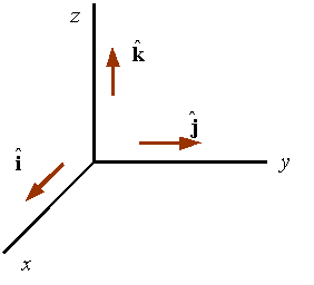
Three-dimensional coordinate axes with z pointing up, y pointing right and x pointing toward the lower left, with unit vectors k-hat along z, j-hat along y and i-hat along x.
 
Last edited:
Is there a figure that goes with this question? Please use the "Attach files" link below the Edit window to upload a PDF or JPEG version of the figure. Thanks.

Also, what are the Relevant Equations for figuring out which way a (magnetized or non-magnetized) needle will point in a magnetic field? :wink:

(and what is "RHTR"?)
 
  • Like
Likes   Reactions: Darshit Sharma
What are you talking about? Please post a picture and clearly explain what it is showing. It's OK to assume that your compass needle is mounted so that it could rotate at any angle.
 
kuruman said:
What are you talking about? Please post a picture and clearly explain what it is showing. It's OK to assume that your compass needle is mounted so that it can rotate at any angle.
Done and Sir do I need to open another thread to ask if the SNOW rule and the ampere swimming rule are completely wrong? Or it will be ok to continue that in my old thread? Just that is the last thing there it was connected so I asked there.
 
Darshit Sharma said:
Homework Statement: In which direction will the needle point?
Relevant Equations: Right Hand Thumb Rule

we re going to have either +j cap or -j cap direction by drawing out the tangent at the point where the needle is kept.
What's a "j cap" direction? Is the needle magnetized or non-magnetized? It would also help if you could make a better 3-D drawing including the coordinate axes (or better yet upload a figure from your textbook on this question).

Darshit Sharma said:
do I need to open another thread to ask if the SNOW rule and the ampere swimming rule are completely wrong?
Sorry, what in the world are those?
 
berkeman said:
Where in this figure are you placing your needle?
perpendicular to the plane of the magnetic field.
 
Darshit Sharma said:
perpendicular to the plane of the
magnetic field.
So parallel to the wire? That will be a pretty unstable position, but if balanced perfectly the ferrous needle would not rotate. It would do something else instead -- can you say what and why?
 
berkeman said:
Sorry, what in the world are those?
The condensation of my doubt regarding them is the correctness of this explanation on this site.

The deflection should be towards the right if I ain't mistaken.
 
berkeman said:
So parallel to the wire? That will be a pretty unstable position, but if balanced perfectly the ferrous needle would not rotate. It would do something else instead -- can you say what and why?
Yes yes. Maybe it will rest in any direction? like some kind of "SYSTEM ERROR" for the needle?

And sir (addressed to either (or both) of you @berkeman or(and) @kuruman) are the polarities or the solenoids correct? I had opened a thread previously but it generated a lot of messy replies because I wasn't able to understand a minor but vital thing which led to not properly arriving at the solution.
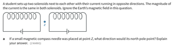
Two solenoids side by side with a small compass needle between them at point Z, with a red and green needle end and blue arrows marking current direction and poles; question text asks which way its north pole points.


The original question was a bit suppressed by my vague doubts, i.e. the first and the original question in the thread below. Could you tell me which (the red or the green part) is the north pole of the magnetized needle?

According to me, green.

Also would you like to check if what I said in my last post on this thread is true? https://www.physicsforums.com/threa...le-between-two-solenoids.1059087/post-6987839
 
Attachments
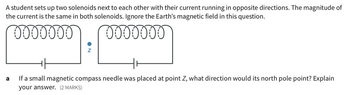
  • Two solenoids side by side with a point Z between them, with a battery under each coil. Text asks which way a compass needle's north pole points at Z.
    1705688332805.png
    23.4 KB · Views: 131
  • Two solenoids side by side connected to batteries, with a point Z between them marked by a dot and label; question asks which way a compass needle's north pole points at Z.
    1705688352023.png
    23.4 KB · Views: 129
Last edited:
I think the needle will rotate downward, M is the magnetic dipole (the needle)

Diagram of magnetic field lines around a horizontal circular current-carrying coil, with a magnetic dipole M marked at the right showing a torque arrow and a blue B arrow pointing down.
 
Darshit Sharma said:
The thing is that the needle is kept in the same plane as the wire
Here is a picture showing current in a long wire coming out of the screen. If you place a magnetic needle in the same plane as the wire (seen edge-on as a gray line), it will point up if it is on the right side of the wire and down if it is on the left side of the wire.
Diagram of concentric circular magnetic field lines around a wire seen end-on, with the wire's cross-section at the centre; a gray horizontal line marks the plane of the wire and the label reads Current is coming out of the screen.


Your picture in post #1 should look like what I show below. Note that the current is reversed from yours because I couldn't find a picture on the web with the current up. Note that the needle is in a plane perpendicular to the wire.
Diagram of a long vertical wire passing up through a flat horizontal board, with three circular arrows around it showing the magnetic field direction, a magnetic compass on the right, and a downward arrow labelled I showing current below the board.
 
  • Informative
Likes   Reactions: Darshit Sharma
Oh wow I totally misunderstood the question. But the idea is the same.
 
PhDeezNutz said:
Oh wow I totally misunderstood the question.
How is that possible? Everything is so crystal clear... :wink:
 
  • Haha
Likes   Reactions: Darshit Sharma and PhDeezNutz
Alright here is a correction
Two diagrams of the right hand thumb/grip rule: left, a hand wrapped around a vertical wire with thumb pointing up along current I and curled fingers showing circular field B; right, a vertical wire with concentric circular magnetic field loops, current arrows up and down, and a torque = m x B vector diagram with m pointing up and B into the page.
##\vec{\tau} = \vec{m} \times \vec{B}##

##\vec{m}## is parallel to the wire (pointing up)

##\vec{B}## points into the page (That's what a X'd circle means)

Take the cross product and ##\vec{\tau}## points inward towards the wire. Meaning it spins into the page to align with the magnetic field.

There we go. I think this is all good now. Apologies to OP.
 
  • Informative
Likes   Reactions: Darshit Sharma
kuruman said:
Here is a picture showing current in a long wire coming out of the screen. If you place a magnetic needle in the same plane as the wire (seen edge-on as a gray line), it will point up if it is on the right side of the wire and down if it is on the left side of the wire.View attachment 338849

Your picture in post #1 should look like what I show below. Note that the current is reversed from yours because I couldn't find a picture on the web with the current up. Note that the needle is in a plane perpendicular to the wire.View attachment 338857
Okok Done question is solved. Thanks sir
 
PhDeezNutz said:
Alright here is a correction View attachment 338858##\vec{\tau} = \vec{m} \times \vec{B}##

##\vec{m}## is parallel to the wire (pointing up)

##\vec{B}## points into the page (That's what a X'd circle means)

Take the cross product and ##\vec{\tau}## points inward towards the wire. Meaning it spins into the page to align with the magnetic field.

There we go. I think this is all good now. Apologies to OP.
Thanks sir