Noise due to chattering of relay

  • Thread starter Thread starter Nikhil N
  • Start date Start date
  • Tags Tags
    emi noise relay
Nikhil N
Messages
80
Reaction score
2
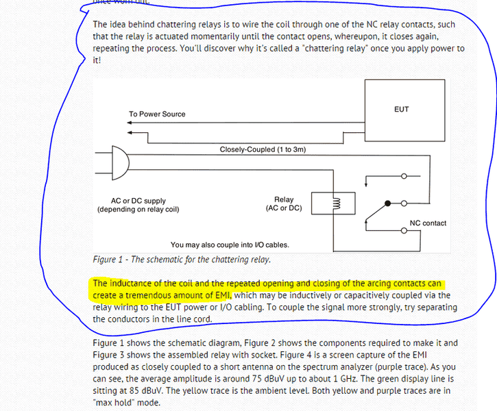
I need to know how to couple noise due to chattering of relay? I have seen the below method to couple. But I want more detailed circuit to do this. Please help me. Also I want to know where the tremendous amount of EMI can be seen ? Is it across the coil of relay?
55.PNG
 
Engineering news on Phys.org
Nikhil N said:
I need to know how to couple noise due to chattering of relay? I have seen the below method to couple. But I want more detailed circuit to do this. Please help me. Also I want to know where the tremendous amount of EMI can be seen ? Is it across the coil of relay?View attachment 112626
I believe the radiation occurs because when the contact starts to open, the inductance of the coil creates a forward EMF and this then causes the gap to break down again. This breakdown is very fast, and you may know that one of the early radio experimenters, Bose, obtained results using a spark gap at 40 GHz. So we may assume it breaks down in picoseconds. Any energy that is stored in the capacitance of the wires will then be converted into oscillatory energy at all frequencies at which the wires have a resonance. To obtain "good" radiation, I suggest connecting short antennas to each side of the spark gap, to form a dipole, or opening out the wiring each side of the contact to form a loop. Remember that the pulse in the coil itself will be quite slow.
I have used a buzzer of this type, using a little relay, as a source of RF for an impedance bridge, as a wavemeter and for measuring resonant frequencies of tuned circuits etc.
 
tech99 said:
I believe the radiation occurs because when the contact starts to open, the inductance of the coil creates a forward EMF and this then causes the gap to break down again. This breakdown is very fast, and you may know that one of the early radio experimenters, Bose, obtained results using a spark gap at 40 GHz. So we may assume it breaks down in picoseconds. Any energy that is stored in the capacitance of the wires will then be converted into oscillatory energy at all frequencies at which the wires have a resonance. To obtain "good" radiation, I suggest connecting short antennas to each side of the spark gap, to form a dipole, or opening out the wiring each side of the contact to form a loop. Remember that the pulse in the coil itself will be quite slow.
I have used a buzzer of this type, using a little relay, as a source of RF for an impedance bridge, as a wavemeter and for measuring resonant frequencies of tuned circuits etc.
Thanks for the replay. Now what's my doubt is U have suggested to connect small antennas to each of the spark gap, by this u have meant to connect the antennas to the coil ends ? Can I wound the wire to which I have to couple the noise onto the relay casing in order to couple the interference?
 
Nikhil N said:
Thanks for the replay. Now what's my doubt is U have suggested to connect small antennas to each of the spark gap, by this u have meant to connect the antennas to the coil ends ? Can I wound the wire to which I have to couple the noise onto the relay casing in order to couple the interference?
The noise comes from the contact, not from the coil.
 

Similar threads

Replies
12
Views
4K
  • · Replies 3 ·
Replies
3
Views
1K
  • · Replies 17 ·
Replies
17
Views
3K
Replies
37
Views
8K
  • · Replies 13 ·
Replies
13
Views
4K
  • · Replies 5 ·
Replies
5
Views
5K
Replies
14
Views
6K
Replies
12
Views
4K
  • · Replies 46 ·
2
Replies
46
Views
5K
  • · Replies 7 ·
Replies
7
Views
3K