Understanding this Circuit involving Relays

  • Thread starter PhysicsTest
  • Start date
  • Tags
    Circuit
In summary, the conversation discusses a circuit controlled by a microcontroller that is used for phase voltage. The RB4 to RB7 outputs control relays and can be used for changing the star to delta connection. The circuit includes 560K and 10K resistors in series and parallel, with an input voltage of 100V resulting in a micro input voltage of 0.97V or 0.885V depending on the calculation. However, the purpose of the circuit is not fully understood due to lack of details and a readable schematic.
  • #1
PhysicsTest
238
26
TL;DR Summary
I need to understand the hardware circuit.
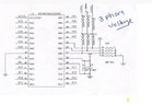
I need to understand the below circuit, the RB4, RB5, RB6, RB7 are controlled by the micro controller. The COM2 and COM3 are going as input to the micro. I know when the outputs RB4 to RB7 are ON, the relays will be ON and 3,4 get shorted. But i don't understand the purpose the circuit. Am i sorry that i don't have much details. Any comments can help me, I heard it can be used to change star to delta connection and vice versa. HardwareDiagram.jpg
 
Engineering news on Phys.org
  • #2
Just to add this is the circuit used for phase voltage, i need to understand. Can I assume that the calculations for Y phase voltage at the micro input is 560K and 560K in series and 10K in parallel
Hence for 100V for example
Voltage at micro = (100*10)/(560K + 560K + 10K) = 0.97V. Please advise, i am not going to design this circuit, this is only for understanding purpose.
 

Attachments

  • VoltageMeasurement.jpg
    VoltageMeasurement.jpg
    21.6 KB · Views: 78
  • #3
PhysicsTest said:
Voltage at micro = (100*10)/(560K + 560K + 10K) = 0.97V.
Check your arithmetic and the missing k multiplier ?
100V *( 10k / ( 10k + 560k + 560k ) ) = 0.885 V
 
  • #4
PhysicsTest said:
But i don't understand the purpose the circuit. Am i sorry that i don't have much details.
The text is important. There is too much white space. Do you have a readable schematic ?
 

1. What is a relay?

A relay is an electrically operated switch that is used to control the flow of electricity in a circuit. It is typically used to turn a high power circuit on or off using a low power signal.

2. How does a relay work?

A relay works by using an electromagnet to control the flow of electricity. When a low power signal is applied to the relay, the electromagnet is activated, which causes the switch to close and allow electricity to flow through the circuit. When the signal is removed, the switch opens and interrupts the flow of electricity.

3. What are the different types of relays?

There are several types of relays, including electromechanical relays, solid state relays, thermal relays, and reed relays. Each type has its own unique characteristics and is used for different purposes.

4. What is the purpose of using a relay in a circuit?

The main purpose of using a relay in a circuit is to control the flow of electricity without directly connecting the controlling device to the high power circuit. This helps to protect the controlling device from damage and allows for easier control of the circuit.

5. How do I choose the right relay for my circuit?

When choosing a relay for your circuit, you should consider factors such as the type of load, the voltage and current requirements, and the switching speed. It is important to select a relay that can handle the specific requirements of your circuit to ensure proper functioning and safety.

Similar threads

  • Electrical Engineering
Replies
32
Views
2K
Replies
31
Views
2K
  • Electrical Engineering
Replies
5
Views
3K
  • Electrical Engineering
Replies
6
Views
1K
Replies
2
Views
2K
Replies
2
Views
2K
  • Electrical Engineering
Replies
10
Views
5K
  • Electrical Engineering
Replies
12
Views
2K
  • Electrical Engineering
Replies
9
Views
3K
  • Electrical Engineering
Replies
1
Views
2K
Back
Top