Discussion Overview
The discussion revolves around the output voltage analysis of an operational amplifier (op-amp) circuit. Participants explore the implications of grounding the positive terminal and the resulting voltage at the output, engaging in a technical examination of circuit behavior and assumptions related to ideal voltage sources.
Discussion Character
- Technical explanation
- Debate/contested
- Mathematical reasoning
Main Points Raised
- One participant asserts that grounding the positive terminal leads to a virtual ground at the negative terminal, expecting the output voltage (Vo) to be 0V.
- Another participant suggests that the problem is a trick question, indicating that the output voltage Vo should still be 0V due to the grounding of the positive input.
- Some participants argue that the non-inverting terminal is not at zero volts, proposing that KVL analysis shows the voltage at that terminal (and the inverting terminal) is equal to 2*V, leading to a gain of 6.
- One participant emphasizes the importance of not shorting ideal voltage sources, arguing that this affects the voltage at the non-inverting terminal and thus the output voltage.
- Another participant challenges the assumptions made in the calculations, stating that if the op-amp is ideal, the output voltage should be 0V unless additional information is provided, such as an offset voltage.
- Some participants express confusion over the circuit schematic and question the validity of the provided answer of 6V, suggesting it may be incorrect based on the information given.
Areas of Agreement / Disagreement
Participants express multiple competing views regarding the behavior of the op-amp circuit, particularly concerning the voltage at the non-inverting terminal and the resulting output voltage. The discussion remains unresolved, with no consensus reached on the correct interpretation of the circuit behavior.
Contextual Notes
Participants highlight limitations in the assumptions made about ideal voltage sources and the implications of grounding in the circuit. There are unresolved mathematical steps and dependencies on circuit configurations that affect the conclusions drawn.
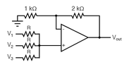
 THE ANSWER IS GIVEN: 6V, but according to me as the positive terminal is grounded the negative terminal will be virtually grounded (0V), from ohm's law (applying to the two series resistance) it is expected that Vo is 0V! I don't know where I am getting wrong!