Question about design active filter

  • Thread starter Thread starter samaaa
  • Start date Start date
  • Tags Tags
    Design Filter
Join the discussion
Registration is free. Ask a follow-up in this thread, or start your own.
4 replies · 3K views
samaaa
Messages
48
Reaction score
0
hi:

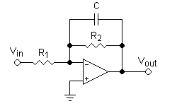
i designed an active low-pass filter,but i don't know if it correct method or not

i want fc=200 Hz and n(order)=4. i use this method:
Active_lowpass_filter.png

by let C=100 nF and use this equation "fc=1/(2*pi*C*R1)"
i get R1= 8 Kohm,R2=R1
this is for one stage

to get filter of 4 order,i repeat that stage 4 times
http://uploadpic.org/storage/2011/M3Oveluhfm4grO0dEPhZiUv.png


so is this method correct?
 
Engineering news on Phys.org
You show four stages, each of 1st order. That will work for an overdamped system (low Q), but if you are designing for a sharp Q (lower damping and with overshoot in its step response), then you'll have to use 2nd order stages. Each comprises 2 capacitors and 2 resistors (at least), and can provide a high Q response (i.e., Q greater than 0.707). In practice, the professional designer faces a bewildering choice, each offering its own set of pros and cons. But for an introduction to the topic there are a few well-tried classics. Any general second-order filter stage will do the job nicely; you'll need two stages.
 
samaaa said:
i want fc=200 Hz and n(order)=4. i use this method:
...
so is this method correct?

No, because your first order filter has a gain of 0.5 at fc=200 Hz.

When you put the four filters in series, the gain at 200 Hz will be ##0.5^4## = 0.0625.

We don't know how much you already know about filter design, so it's hard to give much advice beyond "get a textbook and study it".

You could try Google for "design a low-pass Butterworth filter" (which seems to be what you were trying to do) but you might need to study some more basic ideas first.
 
NascentOxygen & AlephZero thank you very much