palaphys
- 269
- 20
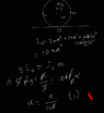
I have a question: if I look at ANY point on the ring relative to some other point, will it be in circular motion? Or is this true only relative to the geometric center of the ring and IAOR?Lnewqban said:... and to the imbalance of masses around the ring: that is the driving torque.
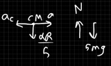
If you take your point of view as the center of the ring, you will see the ring pushing the surface rearward.
In order to do that, the ring needs "to be able to grab" onto the surface.