Simple puzzle: bicycle motion

  • Thread starter Thread starter DaveC426913
  • Start date Start date
Join the discussion
Registration is free. Ask a follow-up in this thread, or start your own.
50 replies · 3K views
It's a simple application of Newton's Second Law.
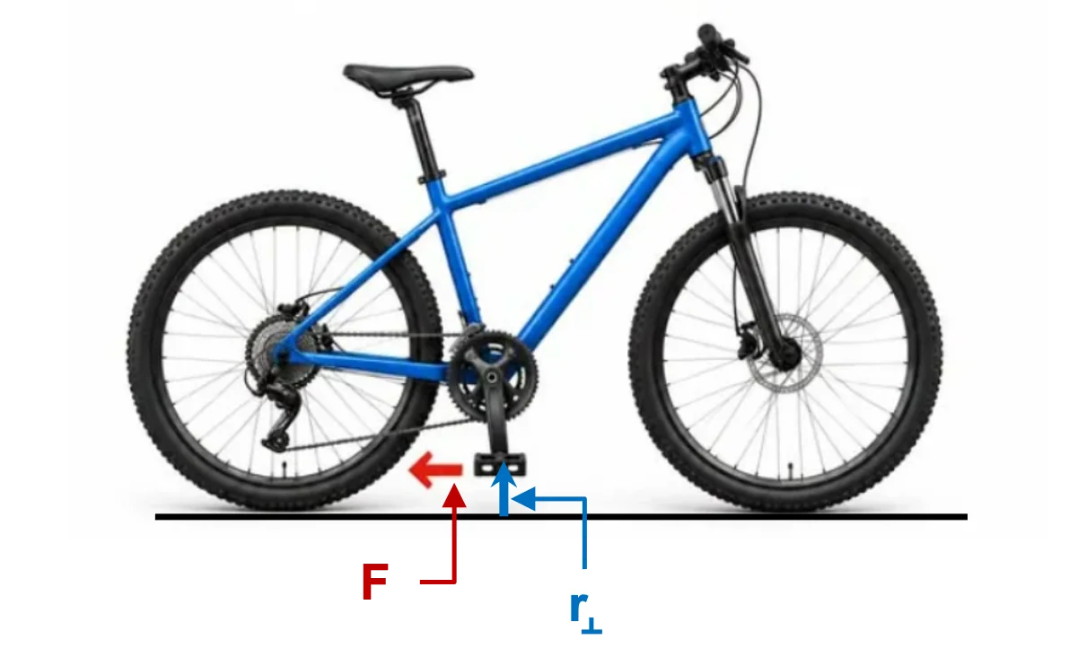
Bike Torque.webp
(a) If the bicycle rolls without slipping, the IPOC (Instantaneous Point Of Contact) of the wheels and the floor is at rest regardless of which way the bicycle moves.
(b) Tie a piece of string on either pedal and pull standing behind the bike with force ##\mathbf F## as shown in the modified figure from post #1.

The bicycle will accelerate to the left according to Newton's Second Law for translational motion. The wheels will acquire counterclockwise angular acceleration according to Newton's Second Law for rotations due to the counterclockwise torque ##\tau=Fr_{\perp}## relative to the IPOC.

People who believe that it is possible for the bicycle to accelerate forward, must also believe that "you can push with a rope." :rolleyes:

Bonus question for the spool "paradox" enthusiasts. It is a screenshot from my insight post.
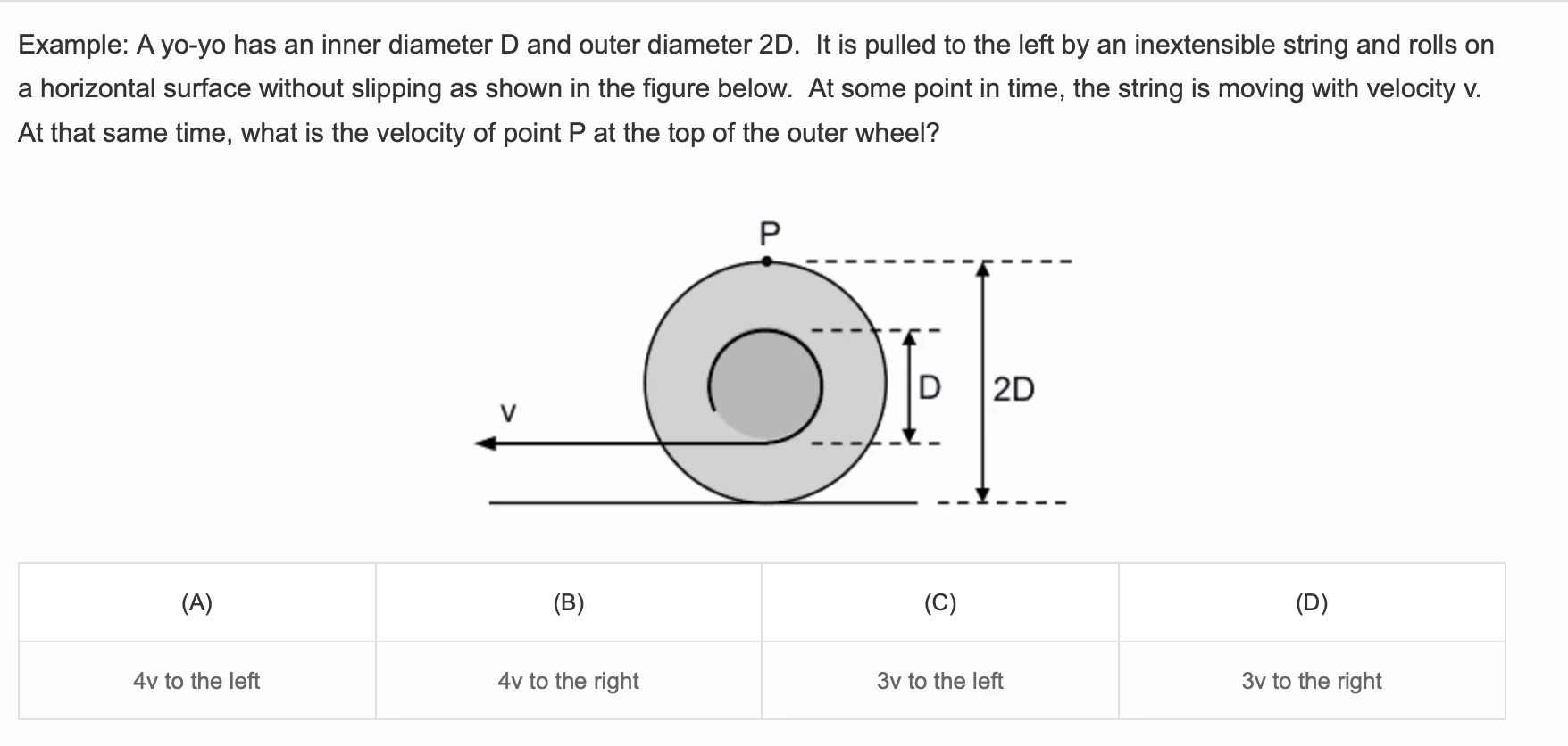
Screenshot 2026-10-01 at 12.17.44 PM.webp

(A) 4v to the left
 
Last edited:
Engineering news on Phys.org
kuruman said:
The bicycle will accelerate to the left according to Newton's Second Law for translational motion.

bike-torque-webp.webp

Newton's Second Law is:

Fnet = ma where Fnet is the sum of all forces.

You have failed to include the forward force of static friction by the ground on the back tire, that will be there if you apply a force to the pedal like that. So you have two opposed forces, and the gearing determines which one is greater.

kuruman said:
People who believe that it is possible for the bicycle to accelerate forward, must also believe that "you can push with a rope." :rolleyes:
No. They are simply people who understand Newton's Second Law and mechanical advantage. You should have watched the video in post #3 at 2:30 before posting:

 
Last edited:
A.T. said:
Newton's Second Law is:

Fnet = ma where Fnet is the sum of all forces.

You have failed to include the forward force of static friction by the ground on the back tire, that will be there if you apply a force to the pedal like that. So you have two opposed forces, and the gearing determines which one is greater.


No. They are simply people who understand Newton's Second Law and mechanical advantage. You should have watched the video in post #3 at 2:30 before posting:


It could be argued that the video is solving a slightly different problem which was not implied by the OP. I consider varying the gear ratios to be a separate problem.
 
bob012345 said:
It could be argued that the video is solving a slightly different problem which was not implied by the OP. I consider varying the gear ratios to be a separate problem.
It isn't a separate problem because the gear ratio determines in which direction the bike will move.

Assuming a typical bicycle gear ratio to answer the question for a typical bicycle is fine.

But ignoring the gear ratio and misapplying Newton's 2nd Law is an incorrect analysis, even if it leads to the same answer for the mere direction as assuming a typical bicycle gear ratio. With just two possible directions you could just was well be guessing. But when you try to predict the speed or acceleration of the bicycle from the pull speed or force, you will get the wrong answer with the approach by @kuruman.
 
Trike.webp
It is true that I was not thinking of gear ratios but a more simplified version such as a tricycle with no gears. The trike will move forward regardless of whether you pull with the yellow force or the red force.
 
kuruman said:
It is true that I was not thinking of gear ratios
That was just part of the problem. The other part was that you ignored the force of the ground on the back tire when applying Newton's 2nd Law.

kuruman said:
but a more simplified version such as a tricycle with no gears.

trike-webp.webp
Yes, this tricycle doesn't have multiple gears, just one fixed gear ratio, determined by the ratio of pedal crank arm length to front wheel radius. Using such a trike for the puzzle in the OP would have been less ambiguous.

kuruman said:
The trike will move forward regardless of whether you pull with the yellow force or the red force.
Yes, but when applying the force to the bottom pedal you still have two opposed forces, which you both have to include when applying Newton's 2nd Law: For the same pull force at bottom vs. top pedal you will get different trike accelerations. Or in kinematic terms: for the same pull speed at bottom vs. top pedal you will get different trike speeds.

Also note that you can modify the trike so it goes opposite to the horizontal pull at the bottom pedal. You just have make the pedal crank arm longer than the front wheel radius (and put the wheels on elevated rails, so the bottom pedal fits beneath them). This is basically what Steve Mould did for the spool here at 5:53:

 
Last edited:
I just looked at this. We have a force of magnitude ##F_1## applied to the left (backwards). This, through the gearing mechanism, also produces a clockwise torque on the back wheel of ##\tau_1 = rF_1##, where ##r## is a gearing factor, with dimension of length.

The friction between the back tyre and the surface creates a second force of magnitude ##F_2## to the right (forwards). This force is variable (up to the maximum possible by static friction). This force produces an anti-clockwise torque of ##\tau_2 = F_2R## on the back wheel, where ##R## is the radius of the back wheel.

Given we have rolling without slipping, we can calculate ##F_2## in terms of the other quantities, where ##M## is the mass of the bicycle and ##I## is the moment of inertia of the back wheel. This gives:$$F_2 = \bigg [ \frac{I +mrR}{I + mR^2} \bigg ]F_1$$The direction of motion, therefore. depends on the relationship between ##r## and ##R##.

If ##R > r##, then ##F_2 < F_1## and the bicycle moves backwards.

If ##R < r##, then ##F_2 > F_1## and the bicycle moves forwards.
 
bob012345 said:
Are you saying a free body diagram would not help for this problem?
If you think that it will help you, then you can draw one.


But when you see a question like the one below, do you also need a free body diagram to answer it? No forces, torques or inertial parameters are given or asked for. Instead only kinematics are given and asked for. So does drawing a FBD with force arrows really help here?

szDY-_7b-I6_FRBMtamIvB02iJgjjyzY14utZ8jF9lQ9j&s=10.webp
 
A.T. said:
If you think that it will help you, then you can draw one.


But when you see a question like the one below, do you also need a free body diagram to answer it? No forces, torques or inertial parameters are given or asked for. Instead only kinematics are given and asked for. So does drawing a FBD with force arrows really help here?

View attachment 374460
We routinely tell student to use free body diagrams so I don’t think it wise to argue not to on PF.
 
bob012345 said:
We routinely tell student to use free body diagrams so I don’t think it wise to argue not to on PF.
We tell students to use FBDs when FBDs are the appropriate tool to solve the problem, yes?

Using FBD on everything is tantamount to having a hammer and seeing everything as a nail. That's not good mathing.
 
DaveC426913 said:
We tell students to use FBDs when FBDs are the appropriate tool to solve the problem, yes?

Using FBD on everything is tantamount to having a hammer and seeing everything as a nail. That's not good mathing.
Why is one not appropriate in this case? That's what I used.
 
bob012345 said:
We routinely tell student to use free body diagrams ...

For any problem?

bob012345 said:
... so I don’t think it wise to argue not to on PF.

You think it is "wise" to draw a FBD and analyze the forces, just to answer the question below?

_7b-i6_frbmtamivb02ijgjjyzy14utz8jf9lq9j-s-10-webp.webp
 
kuruman said:
Bonus question for the spool "paradox" enthusiasts.
Let me give you a gift in return.

A rigid body consists of two coaxial spools of radii ##r## and ##R,\quad R>r.## The outer spool can roll on the plane without slipping. A string is wound around the inner spool and pulled by end ##B## with a velocity of constant magnitude ##v## and directed along the straight portion ##AB## of the string. It is known that at the initial moment, the angle of inclination of the straight portion of the string is equal to ##\hat\alpha\in (0,\pi/2)## and ##AB=\ell##. Find the dependence of the length ##AB## on ##\alpha## in the subsequent motion. ##r\ne R\cos\hat\alpha.##
1.webp
 
Last edited:
PeroK said:
Why is one not appropriate in this case? That's what I used.
This problem can, of course, be solved by elementary means. A bicycle consists of 4 rigid bodies (the frame, two wheels, and the pedals). For each body, one needs to set up a system of equations of motion accounting for reaction forces—there may be some indeterminate constraints somewhere—add kinematic equations, and rigorously solve this entire system. 12 dynamical equations+ several kinematic equations.
 
A.T. said:
For any problem?
When forces are involved.
A.T. said:
You think it is "wise" to draw a FBD and analyze the forces, just to answer the question below?
Yes. At least in my head.
 
bob012345 said:
When forces are involved.
Consider this question:

You push a box for 1 m along a 30° incline upwards. How much height has the box gained?

Does it make sense to draw a FBD with all forces involved to answer the above question?
 
A.T. said:
Consider this question:

You push a box for 1 m along a 30° incline upwards. How much height has the box gained?

Does it make sense to draw a FBD with all forces involved to answer the above question?
Just because I can do it in my head does not make it good practice for a student in my opinion. If it were in my class I would expect the student to draw something to make it clear they understand the problem setup. If it were a problem on a quiz or test and they just write “0.5” how do I know they didn’t just copy it? I consider it part of showing their work. As you might surmise, I don’t think much of multiple choice questions for physics.
 
PeroK said:
Why is one not appropriate in this case?
It's OK, but Is it actually needed to answer the question, or just a detour?

PeroK said:
That's what I used.
Just to find that the final answer depends only on the geometrical parameters ##R## and ##r##, and thus could have been derived using a purely kinematic approach, without ever mentioning forces or moments of inertia.
 
bob012345 said:
We routinely tell student to use free body diagrams
A.T. said:
For any problem?
bob012345 said:
When forces are involved.
A.T. said:
Consider this question:

You push a box for 1 m along a 30° incline upwards. How much height has the box gained?

Does it make sense to draw a FBD with all forces involved to answer the above question?
bob012345 said:
... I would expect the student to draw something to make it clear they understand the problem setup...
So despite forces being involved we don't need a FBD with forces, just "something to make it clear they understand the problem setup"?
 
A.T. said:
It's OK, but Is it actually needed to answer the question, or just a detour?


Just to find that the final answer depends only on the geometrical parameters ##R## and ##r##, and thus could have been derived using a purely kinematic approach, without ever mentioning forces or moments of inertia.
A FBD is reliable technique for a problem like this. Especially as the problem has been presented as something tricky and possibly counter-intuitive. Those are precisely the problems where it's best to fall back on tried and trusted techniques.
 
PeroK said:
A FBD is reliable technique for a problem like this.
But it's not the only reliable technique. And for a purely kinematic problem it's unnecessarily complicated, which introduces additional occasions for errors, making it less reliable in the end (see the attempt in post #31).

You got it right, but you could have made your life easier by defining just one parameter for the mechanical advantage of the bike: ##A = \frac{r}{R}## (where ##r## & ##R## are your two parameters), and arrive at the formula in the diagram below leading to the same conclusions, without any use of forces or inertial parameters.

2ovvw6q-png-webp.webp