
Learn The Basics of Rolling Motion
Table of Contents
Introduction
Although rolling wheels are everywhere, when most people are asked “what is the axis of rotation of a wheel that rolls without slipping?”, they will answer “the axle”. It is an intuitively obvious answer shared by 3/4 or more of the students in an introductory physics class. It is also the wrong answer. Here I describe an incremental teaching method that compels students to come face-to-face with their preconceptions concerning rolling motion. I then offer some speculation on how these preconceptions could have taken hold and suggest ways to assess how well this method works.
Setting the stage
Definition of the axis
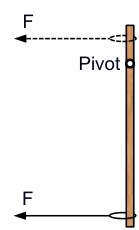
I begin by defining the axis of rotation of a rigid body as the set of all points that are (instantaneously) at rest while all the other points rotate about it with angular speed ## \omega ##. I use a meter stick mounted vertically and free to rotate about a nail going through a hole drilled at some distance from the midpoint (see figure below).
Meter stick demonstration and rule
By pulling with a string below and above the pivot (solid and dashed lines) I establish the rule that relates the sense of rotation to the point of application of a force directed to the left: Clockwise ## \rightarrow ## below the pivot, counterclockwise ## \rightarrow ## above the pivot. Although this seems to be a trivial observation that everyone can understand and accept intuitively, I write it on the board for the students to see so that I can refer to it later.
Theory
Majority belief and theoretical argument
First I establish the size of the majority by asking “How many of you believe that the axis of rotation of a rolling wheel is at its center?” Then I proceed to show that the axis of rotation is the instantaneous point of contact (IPOC) with the table. The argument is simple: if the wheel is to roll without slipping, the point on the wheel that is in contact with the table must be instantaneously at rest concerning the corresponding point on the table. If not, the two points will rub past each other and the wheel will be slipping. Therefore, by the definition of the axis of rotation, the IPOC is the axis of rotation while the other points of the wheel rotate about it. So much for the theory. At this point, I ask how many students (a) believe that the axis of rotation is the IPOC, (b) believe that the axis of rotation is the center, or (c) don’t know what to believe. Few students vote (a) while a healthy percentage plays it safe with (c). Preconceptions are based on misunderstood or misinterpreted observations. To dislodge them, theoretical arguments need to be bolstered by correctly guided observation.
Verification
Yo-yo 1 demonstration
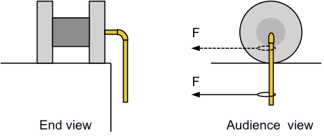
I bring out yo-yo 1. It is a discarded cable spool furnished with a side arm, and a short piece of PVC tubing attached to the center of the spool. The other end of the short piece is attached, through an elbow joint, to a longer PVC piece hanging vertically. The contraption is placed near the edge of the table with the side arm hanging straight down (see figure below).
Observations and precautions
First I pull on the string at a level below the tabletop which results in a clockwise rotation of yo-yo 1. According to the rule on the board, the force is exerted at a point below the pivot. No problem with anyone. Next, I raise the string to a point below the center of the wheel, but above the tabletop (dashed line). Before I pull on the string, I remind the rule to the audience, Clockwise ## \rightarrow ## below the pivot, counterclockwise ## \rightarrow ## above the pivot. When I pull, the rotation is counterclockwise. I conclude that the pivot must be somewhere between the two positions. Since theory predicts that it is at the point of contact, I place the string at the same level as the tabletop. When I pull, there is no rotation. Note: If you try this, be careful not to pull too hard, else the yo-yo will rotate about the vertical axis that has a non-zero lever arm. A rubber mat makes the contact less slippery.
The reality check
Prediction and can experiment
After reinforcing the theory with the experiment it is time to use the theory to predict an outcome and verify the prediction by experiment. If the IPOC is indeed the axis of rotation and if the entire wheel rotates about with angular speed ## \omega ##, then the center of mass will have linear speed ## V_{CM} = \omega R, ## where R is the radius of the wheel. I predict that the top point on the rim of the wheel, which is diametrical across the point of contact, must have speed ## V_{top} = \omega (2R)=2 V_{CM}##. To validate this prediction, I placed a soda can on the table and a meter stick on top of the can parallel to the tabletop. The 0 cm mark is lined up with the top of the can. The starting point of both the center of the can and the edge of the meter stick are marked with a small object placed on the table. I then push the meter stick forward so that the can roll without slipping on both the table and the meter stick. I stop when the top of the can is at about the middle of the meter-stick and mark the new positions of the can’s center and the 0 cm mark. It is clear that, in the same amount of time, the 0 cm mark is twice as far from the center of the can. Therefore, the top point can move at twice the average speed of the center in agreement with the theory.
Are we there yet?
Student assessment and yo-yo 2
A theoretical prediction has been made and an experiment verified it. I ask the students if they are now convinced that the POC is the axis of rotation and most of them are. But wait, there is more! To see if they got it, I bring out yo-yo 2. This is another spool with a string wrapped around the inner cylinder. First I wrap the string so that it comes off the cylinder parallel to the table from the top (figure below left). When I ask, an overwhelming percentage of students say that the cylinder will roll to the left, in the same direction as the pull. Hurray, that is what happens when I pull.

I then flip yo-yo 2 over, so that now the string comes off the cylinder parallel to the table from the bottom (figure above, right). When I ask, an overwhelming percentage of students say that the cylinder will roll to the right, in the opposite direction as the pull. Alas, that is not what happens when I pull. Some students audibly gasped when they saw yo-yo 2 unexpectedly move to the left. At this point, I feign exasperation, point to Clockwise ## \rightarrow below the pivot counterclockwise ## \rightarrow ## above the pivot on the board, and ask, “Is the force not acting above the point of contact in both cases? What more can I do to get you to accept that the point of contact is the axis of rotation?”
When is the preconception?
Bicycle example
It is a good guess that the preconception at play here is the belief that the axis of rotation is always the center of the wheel. This is coupled with the inability to transform from moving to a stationary frame consistently. If one rides a bicycle and looks straight down at the front wheel, one sees a stationary axle with the wheel turning around it. Specifically, the bottom of the tire touching the ground is seen moving backward while the top of the tire moving forward. One also sees the ground rush past backward, but one dismisses this observation as merely an appearance because one “knows” who is “really” moving and it is not the ground. Thus, one fails to realize that the point of contact of the tire and the ground are moving at the same speed and, therefore, that they are at rest concerning each other. So when one sees someone else riding a bicycle, one erroneously thinks that the point of contact is moving, just like it was moving when riding the bicycle. The preconception arises as a result of incomplete and misinterpreted observation.
Toilet-paper intuition
I also hypothesize that the preconception involved with yo-yo 2 arises from intuitive ideas adopted by the observation of unrolling toilet tissue or paper towels, items intimately familiar to everyone. Imagine yo-yo 2 (the previous figure left) being a roll of toilet tissue in its dispenser. If pulled as shown in the figure left, it will spin counterclockwise in place. No problem here. Now, if the roll is placed on a tabletop and then pulled, the intuitive prediction is that the roll will spin counterclockwise and as a result roll to the left. That the axis of the roll is no longer constrained to be immobile, thus any longer serving as the axis of rotation, is not taken into account. Furthermore, when the experiment is performed, the result matches the prediction. This validates in one’s mind not only the prediction but also the inappropriate analysis that led to it. One then carries this faulty reasoning to “flipped over” yo-yo 2 (previous figure right.) If pulled, “obviously” the string will unravel clockwise resulting in a translation of the roll to the right. The new scientifically established rule on the board has apparently been set aside in favor of intuitive beliefs compiled after years of observing unwinding rolls of paper.
Follow-up
The effectiveness of the method can be quantified by using clickers to monitor the ebb and flow of student understanding as it develops. I have not done that, but I test the persistence of the preconception by putting a multiple choice question on the next hourly test.
In-class test example
Example: A yo-yo has an inner diameter D and outer diameter 2D. It is pulled to the left by an inextensible string and rolls on a horizontal surface without slipping as shown in the figure below. At some point in time, the string is moving with velocity v. At that same time, what is the velocity of point P at the top of the outer wheel?
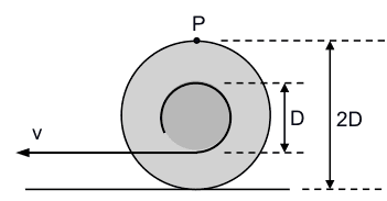
| (A) | (B) | (C) | (D) |
| 4v to the left | 4v to the right | 3v to the left | 3v to the right |
The correct answer is (A). Students who answer (B) or (D) are likely to confuse the rolling motion with the spin of a paper roll about a fixed axis. Students who answer (C) or (D) are likely to be clinging to the idea that the axis of rotation is at the center of the yo-yo. When I ask this question, 40%-50% of the students get it right. Answer (B) comes second at about 20%. I don’t have baseline data from a control group of students who have answered the question without the benefit of the demonstrations, but I believe the method works.
I am a retired university physics professor. I have done research in biological physics, mostly studying the magnetic and electronic properties at the active sites of biomolecules and their model complexes. I have also dabbled in Physics Education research.


It looks like you missed the point that when the force is applied at a point that is vertically even with the IPOC, there is no torque generated by that force. This level marks the threshold below which the torque is in one direction and above which it is in the opposite direction. Given that information, at what level would you say the axis of rotation is?If I apply a force at the IPOC I will either slow down or speed up the rotation, unless friction between the surface and the wheel prevents that force from actually acting on the wheel.
Use a cylinder rolling on two rails to demonstrate.
The starting assertion should (IMO) be, applying force on one side of the axis creates rotation in one direction, applying it to the other creates rotations in the other, and applying force at the axis causes no rotation.
Yes, one certainly can analyze the problem using the IPOC, but it is not the only way to do it, and I don't really see that you have proved anything.It looks like you missed the point that when the force is applied at a point that is vertically even with the IPOC, there is no torque generated by that force. This level marks the threshold below which the torque is in one direction and above which it is in the opposite direction. Given that information, at what level would you say the axis of rotation is?
You started with a seemingly arbitrary assertion about direction of rotation and application of force, then you "prove" your point by applying force to the center of the spool while pretending to apply it elsewhere using the pvc pipe.
Yes, one certainly can analyze the problem using the IPOC, but it is not the only way to do it, and I don't really see that you have proved anything.
If we choose C as the axis (dropping the restriction that an axis must be "at rest"), as most people intuitively do, none of those problems occur.I agree. However, I am examining the situation from the inertial frame of the table not the non-inertial frame of the wheel.
Also, you still haven't explained how you're dealing with the fact that the IPOC Q is at a different place at every point in time. How is that compatible with it being at rest?Please examine the drawing in post #43. Point Q is not moving relative to the surface. If Q were the IPOC, it would be drawn directly underneath point C.
But this is not enough to make this motion a rotation.That's a matter of opinion. Consider the simpler case of a block sliding on a frictionless surface. C in the figure marks the center of mass and point Q is fixed on the surface. The block has constant angular momentum ##L=mV_cR## relative to Q. Now consider force ##F## acting on C. Clearly the angular momentum will change because the velocity will change. Changing angular momentum implies the action of a non-zero torque. Non-zero torque implies non-zero angular acceleration. Non-zero angular acceleration implies changing angular velocity. Angular velocity implies rotation about a center, in this case Q because that's the point about which the angular momentum is expressed. To me this chain of reasoning is sufficient to justify rotation even when there is no rolling motion.
One can always replace cartesian coordinates with polar coordinates.I'm not disputing that you can choose whatever coordinate system you like to describe the situation. I'm just saying that it's very unnatural to call it a "rotation", for the following reasons:
If we choose C as the axis (dropping the restriction that an axis must be "at rest"), as most people intuitively do, none of those problems occur.
Also, you still haven't explained how you're dealing with the fact that the IPOC Q is at a different place at every point in time. How is that compatible with it being at rest?
If a point travels along ##begin{pmatrix}t\1end{pmatrix}## in cartesian coordinates, you can of course express this with polar coordinates with a changing radius and a changing angle. But this is not enough to make this motion a rotation.
Please reread my post #43. My arguments apply to the inertial frame of reference. "Straight down" is not defined as the "centripetal direction". The centripetal direction is defined as the direction from the point of interest to the center of rotation. As seen in the figure, if point Q is the chosen center of rotation, point C rotates about Q with angular speed as derived.
… as is obvious for a linear motion with constant velocity.Not so. It looks like you are limiting your thinking to one-dimensional motion. Examine the figure. Point C undergoes linear motion at constant velocity, true enough. Yet, relative to point Q, its velocity has a radial component (the radius being the line joining Q and C) and a tangential component. In two dimensions, point C moves radially away from Q while at the same time rotates clockwise about Q. One can always replace cartesian coordinates with polar coordinates.
The centripetal direction is not straight up as you assert, but straight down.I wasn't talking about C but P.
$$V_C=frac{dx}{dt}$$And since ##V_C## is constant, it follows that ##a_C=frac{d^2x}{dt^2}=0##, hence C is not accelerated, as is obvious for a linear motion with constant velocity.
If point C is rotating about Q, what is the centripetal direction?Of course you can define straight down as the "centripetal direction", but this doesn't change the fact that C is not accelerated towards that direction as it should be in a rotation. In fact the only point on the wheel accelerated towards Q is the uppermost point of the wheel, but the magnitude of the acceleration is wrong for a rotation around Q with ##omega##. Point P is even accelerated away from Q.
How can you claim that Q is at rest but the center of the wheel is not?I don't believe I made (or implied) such a claim.
In the inertial frame of the table,
1. Q is at rest because it is a point on the table.
2. P (on the rim of the wheel) is at rest with respect to the surface because the wheel is rolling without slipping.
3. The center of the wheel, C, is moving to the right (say) with speed V[SUB]C[/SUB].
Therefore the center of the wheel is moving to the right with speed V[SUB]C[/SUB]. The translational motion of the center can also be construed as rotational motion about Q with the angular speed ω = V[SUB]C[/SUB] / R. The centripetal direction is not straight up as you assert, but straight down.
Here is a formal derivation. Consider the center C at some point in time when it is not directly above Q and is moving parallel to the surface to the right (see figure below). At that point, we have
$$x = R tan theta$$
$$V_C=frac{dx}{dt}=R(tan^2 theta+1)frac{dtheta}{dt}=R(tan^2 theta+1)omega$$
$$omega = frac{V_C}{R(tan^2 theta+1)}$$
Point C is rotating about Q with angular speed ##omega## as expressed above. If point C is rotating about Q, what is the centripetal direction?
View attachment 214890
When C is directly above Q, ##theta = 0## and ##omega=V_C/ R##. What is the centripetal direction now?
Well you can't have both
No, the IPOC is on the inertial frame of the table.and
They are. […] In what direction is the centripetal acceleration relative to the point of contact?While
The instantaneous velocity vector of the point of interest on the rolling wheel is perpendicular to the position vector from the point of contact to the point of interest.is true for both P and Q, the centripetal acceleration vectors of points on the wheel are only directed to P in its rest frame (which is not inertial, but accelerated upwards), not to Q in its rest frame (the inertial frame of the table). If a wheel rotates with constant ##omega##, the centripetal acceleration of all points is directed radially inwards, adding a constant velocity doesn't change that.
How can you claim that Q is at rest but the center of the wheel is not? They are exactly above each other at each point in time, and the center of the wheel is obviously movint to the right.
No, the IPOC is on the inertial frame of the table. Let P be the point of contact on the wheel and Q be the point of contact on the surface. If the wheel rolls without slipping, points P and Q are at rest relative to each another. However, point P has an upward acceleration in the inertial frame of the surface whereas point Q has zero acceleration in that same frame. The inertial frame to work in is the table surface with Q as the origin. Consider an arbitrary point S on the wheel defined by position vector ##vec{r}_S## from point Q to S. Then the velocity of point S (relative to point Q), ##vec{V}_S##, is perpendicular to ##vec{r}_S##. If the center of the wheel is moving with velocity ##vec{V}_C##, then the angular velocity is ##omega=V_C/R##. This makes the speed ##V_S=omega~r_S=V_C(r_S/R)##.
In what direction is the centripetal acceleration relative to the point of contact?Sorry, I've misunderstood. I thought the IPOC was on the table, while it's actually on the wheel. But this means you're working in an upwards accelerated frame. Did you really intend to treat this in a non-inertial system?
"I begin by defining the axis of rotation of a rigid body as the set of all points that are (instantaneously) at rest while all the other points rotate about it with angular speed ω."Perhaps I should have said "… the set of all points that are (instantaneously) at rest [color = red]with respect to the chosen frame of reference[/color] while … ". All motion is relative and I pick the axis of rotation to be at rest relative to whatever frame of reference one chooses to express velocities.
Isn't that an unusual, coordinate-dependent definition of rotation?I don't think so. It is based on what I said above. It indeed is coordinate-dependent, but it is not unusual because it defines the axis of rotation in the whatever reference frame has already been chosen.
… why aren't the points on the wheel accelerated towards it?They are. The instantaneous velocity vector of the point of interest on the rolling wheel is perpendicular to the position vector from the point of contact to the point of interest. In what direction is the centripetal acceleration relative to the point of contact?
Further abstracting OP's argument, one could describe the motion of a point along $$begin{pmatrix}t\1end{pmatrix} $$by an infinitesimal rotation around the axis at $$begin{pmatrix}t\0end{pmatrix}$$ at each point in time t, which would be quite silly.I don't understand the abstraction. Can you explain it, especially the part that is silly?
"I begin by defining the axis of rotation of a rigid body as the set of all points that are (instantaneously) at rest while all the other points rotate about it with angular speed ω."
Isn't that an unusual, coordinate-dependent definition of rotation? Why do you demand the axis to be at rest? If you drop this condition, the centre immediately becomes an option too.
I don't even think the argument is consistent. If I understand your definition of the IPOC correctly, each of them only exists at a point in time, so they don't even have a trajectory and the property "at rest" is meaningless.
It might be mathematically convenient to use the point of contact as the pivot point, but this conflicts with the tension within the wheel, which corresponds to the centripetal acceleration of all points about the center of mass, regardless of which inertial frame of reference is being used.Good point. If the IPOC really is the axis of a (non-accelerated) rotation, why aren't the points on the wheel accelerated towards it?
Further abstracting OP's argument, one could describe the motion of a point along ##begin{pmatrix}t\1end{pmatrix}## by an infinitesimal rotation around the axis at ##begin{pmatrix}t\0end{pmatrix}## at each point in time ##t##, which would be quite silly.
[QUOTE="ThingsCanMove, post: 5617984, member: 608548"]Hello all,First post. This is really confusing to me. Lets say I had a solid wheel on the ground being driven by a specific torque without slipping. So with the center of rotation being through the middle of the wheel the Moment of Inertia would be (1/2)*mr[SUP]2[/SUP]. Yet with the center of rotation being the ground the moment of inertia changes to 3/2mr[SUP]2[/SUP]. So if angular acceleration=Torque/I why is the angular acceleration different just based on my reference frame when the wheel is driven by the same torque, it's just two ways of describing the same problem.So I know I'm missing a lot of stuff, please help.”By considering the centre of rotation as the instantaneous point of contact, it is actually harder to visualize and do problems.Usually, where I study, we consider the axis of rotation as any line of symmetry and make necessary adjustments. This way, complications will be avoided.
[QUOTE="ObjectivelyRational, post: 5579771, member: 590927"]How would you respond to a student who raises the issue of "frame of reference" for which the definition of "axis of rotation" is made?For example if a student said in the context of a coin rolling on a table at a constant velocity, "What about from the frame of reference of the center of gravity of the coin? The table is moving in a straight line relative to the COG, the edge is moving without slipping at the same speed as the table, but the coin is rotating about the COG which is stationary (translationally). Why in this frame of reference should the COG not be considered the axis of rotation?"How would/should you respond?”The COG CAN be considered as an axis of rotation. What else could one possibly consider as an axis of rotation? The mathematics would be least complicated when the axis of rotation passes through COG and perpendicular to the plane of the surface of the coin.
To augment what [USER=260864]@vanhees71[/USER] wrote, an arbitrary choice of describing the motion will do the job but it can get messy. Of all the infinite choices, two reference points stand out as giving simple results: the point of contact P and the center of the wheel O. Here is why. Assume the wheel accelerates to the right.1. Choose P as reference. With respect to P, the center of the wheel O has instantaneous speed ##v_O=omega_PR## from which $$omega_P=frac{v_O}{R} rightarrow alpha_P=frac{1}{R}frac{dv_O}{dt}$$2. Choose O as reference. With respect to O, the point of contact of the wheel P has instantaneous speed ##v_P=omega_OR## from which $$omega_O=frac{v_P}{R} rightarrow alpha_O=frac{1}{R}frac{dv_P}{dt}$$In the general case, an observer on the ground sees point O moving to the right with speed ##v_O##. An observer on the wheel (at rest relative to point O) sees point P moving to the left with speed ##v_P## and the ground moving also to the left with speed ##v_O##. In the specific case of rolling without slipping, the ground is instantaneously at rest relative to point P at all times. Therefore, the instantaneous speeds are equal, ##v_P=v_O##, and hence their time derivatives are equal which makes ##alpha_P=alpha_O##.Choosing either one of these frames of reference has the advantage that the acceleration of the center of mass is related to the angular acceleration by ##a_{cm}=alpha R##. Personally, I prefer to use point P as reference because then I don't have to find the force of static friction in order to calculate the torque generated by it.
If you change the body-fixed reference point to describe the motion of the rigid body not only the tensor of inertia changes (according to Steiner's rule) but also the angular momentum and torque. Since the description of the motion of the body is independent on the choice of the body-fixed reference frame (i.e., the body-fixed point and orientation of the body-fixed coordinate basis) all equations must transform consistently. That's why I said above that it is your arbitrary choice how you describe the motion.
Hello all,First post. This is really confusing to me. Lets say I had a solid wheel on the ground being driven by a specific torque without slipping. So with the center of rotation being through the middle of the wheel the Moment of Inertia would be (1/2)*mr[SUP]2[/SUP]. Yet with the center of rotation being the ground the moment of inertia changes to 3/2mr[SUP]2[/SUP]. So if angular acceleration=Torque/I why is the angular acceleration different just based on my reference frame when the wheel is driven by the same torque, it's just two ways of describing the same problem.So I know I'm missing a lot of stuff, please help.
[QUOTE="kuruman, post: 5587259, member: 192687"]I am not sure what you mean by "regular" moment of inertia. As I mention in post#26, one ought to use the moment of inertia about the point of contact P when writing the total kinetic energy as one term. Of course the moment of inertia about P is related to the moment of inertia about the cm through the parallel axes theorem that you quoted, I[SUB]P[/SUB] = I[SUB]cm[/SUB] + md[SUP]2[/SUP], where d is the distance between the point of contact P and the cm. For the rolling wheel, d = R.”Hmm. Assume a self propelled wheel (bicycle) and a big sphere. The sphere being the size of the earth with its COG at its center. Due to conservation of momentum the little wheel spins around its COG while the big sphere VERY slowly spins around its own axis of rotation.The contact point is very important because it is the fulcrum of applied torque(s)… the interaction point between the two bodies that transfers momentum. Still trying to get a sense why there is "one correct" way to look at the system.
[QUOTE="FallenApple, post: 5587196, member: 585259"]Hmm Interesting. So if the axis of rotation is the instantaeous point of contact, then why is the regular moment of Inertia used? Shouldn't it be I[SUB]cm[/SUB]+mR[SUP]2[/SUP].?”I am not sure what you mean by "regular" moment of inertia. As I mention in post#26, one ought to use the moment of inertia about the point of contact P when writing the total kinetic energy as one term. Of course the moment of inertia about P is related to the moment of inertia about the cm through the parallel axes theorem that you quoted, I[SUB]P[/SUB] = I[SUB]cm[/SUB] + md[SUP]2[/SUP], where d is the distance between the point of contact P and the cm. For the rolling wheel, d = R.
Hmm Interesting. So if the axis of rotation is the instantaeous point of contact, then why is the regular moment of Inertia used? Shouldn't it be I[SUB]cm[/SUB]+mR[SUP]2[/SUP].?
True! The choice of the right coordinates is the first step to the solution of a mechanical problem. I don't say that it's wrong to use the momentary point of contact. It's maybe even a clever choice for such problems, but I had a very hard time to understand this when I was a freshmen, while the treatment in the other frame was a piece of cake, but that's of course subjective.
[QUOTE="vanhees71, post: 5587096, member: 260864"]I disagree. You can choose any body-fixed reference point (it can even be a ficitious point outside of the body, it must only be rigid wrt. the body; of course, I assume an idealized rigid body here), and ⃗ωvec{omega} is then related to this point. Of course, ⃗ωvec{omega} changes when you change the body-fixed reference point.”True but not helpful when teaching freshman physics. Of the infinity of points that one is free choose to describe the rotation, the set of points that are at rest with respect to the observer makes the description easier. The geocentric system is not wrong, it just complicates the description of planetary motion. Instead, we use the heliocentric system that assumes an observer at rest with respect to the Sun.
I disagree. You can choose any body-fixed reference point (it can even be a ficitious point outside of the body, it must only be rigid wrt. the body; of course, I assume an idealized rigid body here), and ##vec{omega}## is then related to this point. Of course, ##vec{omega}## changes when you change the body-fixed reference point.
[QUOTE="vanhees71, post: 5586897, member: 260864"]Of course, usually you can simplify the task tremendously by choosing the body-fixed point and frame cleverly. For the orientation of the body-fixed basis it's of course very convenient to choose the principle axes of the tensor of inertia and, if the body is moving freely in space, the center of mass of the body as the body-fixed reference point.”There is something to be said in favor of picking the point of contact as the axis of rotation as far as simplification is concerned. One can always write the total kinetic energy as ## K = frac{1}{2} I_P omega^2 ## where ## I_P ## is the moment of inertia about the point of contact or axis of rotation. One can then use Steiner's (a.k.a. parallel axes) theorem to relate ## I_P ## to the moment of inertia about the center of mass. I adopted this point of view when I found out that students had difficulties "wrapping their head around" the dual concept of kinetic energy of the center of mass and kinetic energy about the center of mass. My method sorts these terms out automatically.[QUOTE="vanhees71, post: 5586897, member: 260864"]That's why I don't think that you can call it a mistake choosing the body-fixed center of the disk as the reference point for the instantaneous angular velocity of the body as claimed in the article.”Although I do not dispute what you are saying in general, I differ with you on this point. It is a mistake within the context of what I am trying to accomplish with this series of demonstrations. Before writing equations of motion for rolling objects, it is necessary for students to have a clear and fundamental understanding of what an axis of rotation is and how to find it. The purpose of the demonstrations is to do just that. Having this understanding is a precursor to describing the motion, whether it be in the lab frame or the CM frame. But OK, perhaps "wrong answer" in the original essay was a harsh label. "Misinformed answer" would have been more appropriate.
[QUOTE="Mister T, post: 5586889, member: 572021"]If you're riding your bike and you look down at the wheel, you see it rotating about the axle. Insisting that it rotates about the point on the rim where it touches the pavement implies a preference for the frame where Earth's surface is at rest”No. It implies a preference for the most difficult to move of the objects touched by the contact points.
It's a nice exercise to show that the motion can as well be described using the one or the other frame. For a rigid body you need just one fixed point and a body-fixed (Cartesian) coordinate system with this fixed point in the origin, and you can describe the kinematics of the body uniquely by looking at the position vector to the fixed point in the body wrt. to an arbitrary inertial (Cartesian) frame and the relative orientation of the body-fixed Cartesian basis to that of the inertial Cartesian basis (e.g., parametrized with Euler angles).Of course, usually you can simplify the task tremendously by choosing the body-fixed point and frame cleverly. For the orientation of the body-fixed basis it's of course very convenient to choose the principle axes of the tensor of inertia and, if the body is moving freely in space, the center of mass of the body as the body-fixed reference point. Also the use of Lagrangian mechanics helps a lot to simplify the task to find the equations of motion.This of course also holds true if you have constraint motions like the rolling disk along an inclined plane as specified in the article. Here the choice of the contact point of the rolling disk seems to be pretty inconvenient since it's not a body-fixed point. Of course, you can get the equations of motion also with respect to this point, but it will lead to the same physical result when choosing the more convenient body-fixed center of the disk as body-fixed reference point. It seems also to be simpler to impose the constraint of "rolling without sliding" condition in this frame. Everything is consistent in any frame and it's also a way to deduce Steiner's theorem on the tensor of inertia (or the moment of inertia around a fixed axis) when changing from one body-fixed reference point to another.That's why I don't think that you can call it a mistake choosing the body-fixed center of the disk as the reference point for the instantaneous angular velocity of the body as claimed in the article.
[QUOTE="kuruman, post: 5585777, member: 192687"]I meant to convey that most people have an intuitive bias favoring the Earth's frame regardless of whether they are moving relative to it or not. “If you're riding your bike and you look down at the wheel, you see it rotating about the axle. Insisting that it rotates about the point on the rim where it touches the pavement implies a preference for the frame where Earth's surface is at rest, but I do not think this is the frame that students would use to think about your question. I think they are putting themselves in the frame where the axis of the wheel is at rest.It is only after careful instruction of the type you're doing that students are able to see things from the frame where the pavement is at rest. While the videos appear to cover this point well, I would wager that they wouldn't create anywhere near the same learning gains as your interactive lessons.
[QUOTE="kuruman, post: 5586099, member: 192687"]Here is a nice demonstrations with a mathematical explanation using trochoids instead of torques about the axis of rotation.”Thanks! Fascinating! I wish I could like that twice!
[QUOTE="A.T., post: 5586113, member: 85613"]A nice variation of this: Fix the loose string end at the top of an incline, put the spool on the incline (with good traction) and ask what will happen when you let it go.”And after you let it go, ask for the tension in the string and the force of static friction at the point of contact.
[QUOTE="kuruman, post: 5585613, member: 192687"]Last diagram being the one in the multiple choice question. Yes, the string gets shorter.”A nice variation of this: Fix the loose string end at the top of an incline, put the spool on the incline (with good traction) and ask what will happen when you let it go.
Here is a nice demo with a mathematical explanation using trochoids instead of torques about an axis of rotation.
https://www.youtube.com/watch?v=aJhiY70KY5o
[QUOTE="A.T., post: 5585980, member: 85613"]Because the pulled string gets shorter?”Yes. Or more precisely, because I figured that out myself and felt unsure about it.
[QUOTE="Collin237, post: 5585958, member: 577701"]I had been baffled by the essay and the diagram;”Because the pulled string gets shorter? Also note that the blue wheel rotates opposite to the torque of by the ruler, and outruns the ruler which it's pushed by:[MEDIA=youtube]k-trDF8Yldc[/MEDIA]
[QUOTE="kuruman, post: 5585777, member: 192687"]For example, say I board a train in New York City headed for Boston. While the train is moving, I dismiss the train's frame of reference, with respect to which I am at rest, and I think of myself as going to Boston, not Boston coming to me. Furthermore, it is a good bet that my fellow passengers share this ambivalent view of reference frames and, if asked, they too will say you that they are going to Boston. The assumption that the Earth is at rest, while we go about our business moving on its surface, is the human way of viewing the world and has become a de facto preferred frame.”It's more subtle than that, I think. Watch someone pouring a drink on the train. They use an inertial approximation to the train frame for that – no-one is carefully considering the effects of trying to pour a drink at high speed in the Earth frame, but when the drink spills they will curse the rocking of the train and not the sudden appearance of fictitious forces. Although I bet if you ask they'll tell you that the table is stationary and not rocking, for which they use the true (non-inertial) train frame. Listen to people looking out of the window and you'll hear both the Earth-centric "we're going really fast" and the train-centric "the houses are going past really fast".As you say, people adopt different reference frames without thinking about it. Disciplining yourself to pick one and stick with it, or at least to only switch consciously, is a big part of any non-trivial dynamics problem, in my opinion.
[QUOTE="kuruman, post: 5585613, member: 192687"]Last diagram being the one in the multiple choice question. Yes, the string gets shorter.”Amazing what seeing a demonstration can do! I had been baffled by the essay and the diagram; but thinking of the spool in the video, now it makes perfect sense.
[QUOTE="Alex Kluge, post: 5585054, member: 523814"]Neither of these reference frames is preferred, and the laws of physics are the same as measured from either frame. These are incredibly important concepts in physics and this example could be a powerful and memorable example for students. So rather than talking about which axis of rotation is correct or incorrect, include how it varies with reference frame.”The symetry of reference frames becomes clear when you consider the walkway carts below, from the rest frame of the walkway. The carts then basically swap their functionality: The one that moved in the same direction (but faster) as the surface moving in the chosen frame, now moves opposite to it. And vice versa.[MEDIA=youtube]pw_B2MnMqZs[/MEDIA]You could show the same even simpler with a spool on a paper strip, or gears on racks, and consider the rest frame of the strip / upper rack:[MEDIA=youtube]E7vcQcIaWSQ[/MEDIA][MEDIA=youtube]dvyii6QBLtw[/MEDIA]
[QUOTE="Alex Kluge, post: 5585054, member: 523814"]This issue may be a little more subtle than your explanation so far. Since you don't explicitly say anything about the reference frame when you ask the original question, an answer framed from the point of view of someone on the bicycle is just as correct as an answer framed from the point of view of someone on the ground.The preconception you mention, is not necessarily a misconception, it is simply a perception from a different point of view, a different reference frame.> one “knows” who is “really” moving and it is not the groundIt almost sounds like you are thinking that the person on the surface of the earth is in a fixed, preferred, reference system. In reality, all we know about the reference frame of the bicycle and the reference frame on the surface of the earth is that they are in motion relative to one another. Neither is truly stationary, and neither is preferred.Neither of these reference frames is preferred, and the laws of physics are the same as measured from either frame. These are incredibly important concepts in physics and this example could be a powerful and memorable example for students. So rather than talking about which axis of rotation is correct or incorrect, include how it varies with reference frame.”When I show this series of demonstrations, the default reference frame is the audience's frame which is fixed to the surface of the Earth. I did not mean to convey that I am thinking "that the person on the surface of the earth is in a fixed, preferred, reference system." I meant to convey that most people have an intuitive bias favoring the Earth's frame regardless of whether they are moving relative to it or not. Physics teaches us that there is no preferred frame. We understand this lesson intellectually but not intutively. For example, say I board a train in New York City headed for Boston. While the train is moving, I dismiss the train's frame of reference, with respect to which I am at rest, and I think of myself as going to Boston, not Boston coming to me. Furthermore, it is a good bet that my fellow passengers share this ambivalent view of reference frames and, if asked, they too will say you that they are going to Boston. The assumption that the Earth is at rest, while we go about our business moving on its surface, is the human way of viewing the world and has become a de facto preferred frame. We have known for centuries that the Earth spins about its axis, yet we still say that the Sun rises in the East and nobody bats an eyelash. Although physics does not have preferred reference frames, everyday life does.Lest this reply be misunderstood, let me reiterate that I do not advocate preferred frames. On the contrary, I do other demonstrations designed to challenge students to see things from other frames of reference including non-inertial ones. These might be the subject of another "Insight" entry.
[QUOTE="kuruman, post: 5579846, member: 192687"]An observer in this moving frame "knows" that (s)he and not the ground is moving.”To follow up on Alex Kluge post about frame of reference, take the case where a coin is rolling on a treadmill such that the center of mass of the coin is not moving with respect to ground, but instead the treadmill is moving with respect to the ground.> spool trickIf the spool was on rails and the hub had a larger radius than the sides of the spool, then pulling the string from under and back from the spool would result in the spool moving forwards. The hub could also be geared so that it rotated faster than the spool, so that string speed is greater than spool rolling speed, and again the spool would move forwards. This would be the same as the second walkway cart at 1:28 into the second video of AT's post.> point of rotation from ground based frame of refernceTo follow up on my prior post, from a ground frame of reference, a point on a wheel follows the path of a cycloid, where the instantaneous acceleration at the point of contact would be zero, and It might be mathematically convenient to use the point of contact as the pivot point, but this conflicts with the tension within the wheel, which corresponds to the centripetal acceleration of all points about the center of mass, regardless of which inertial frame of reference is being used. In my opinion, both views are mathematically correct for a ground based frame of reference, rotation about the contact point, or a combination of linear motion at the center of mass and rotational motion about the center of mass.
[QUOTE="Collin237, post: 5585162, member: 577701"]In the last diagram. Does pulling on the string make the length of the straight part shorter?” [MEDIA=youtube]Bwf3msm7rqM[/MEDIA] [MEDIA=youtube]R3GHiMOHEy8[/MEDIA] [MEDIA=youtube]MOF71tD_BA4[/MEDIA]
Last diagram being the one in the multiple choice question. Yes, the string gets shorter.
In the last diagram. Does pulling on the string make the length of the straight part shorter?
This issue may be a little more subtle than your explanation so far. Since you don't explicitly say anything about the reference frame when you ask the original question, an answer framed from the point of view of someone on the bicycle is just as correct as an answer framed from the point of view of someone on the ground.The preconception you mention, is not necessarily a misconception, it is simply a perception from a different point of view, a different reference frame.> one “knows” who is “really” moving and it is not the groundIt almost sounds like you are thinking that the person on the surface of the earth is in a fixed, preferred, reference system. In reality, all we know about the reference frame of the bicycle and the reference frame on the surface of the earth is that they are in motion relative to one another. Neither is truly stationary, and neither is preferred.Neither of these reference frames is preferred, and the laws of physics are the same as measured from either frame. These are incredibly important concepts in physics and this example could be a powerful and memorable example for students. So rather than talking about which axis of rotation is correct or incorrect, include how it varies with reference frame.
[QUOTE="kuruman, post: 5579846, member: 192687"]Indeed, in the frame moving with the coin, the COG is the axis of rotation. The fact that in the moving frame of reference it is and in the stationary frame it is not gives rise to the preconception that I attempt to explain in the first paragraph of "Whence the preconception?" Let me rephrase my hypothesis. In the moving frame of a rolling wheel, the axis of rotation is the center of the wheel. An observer in this moving frame "knows" that (s)he and not the ground is moving. Put the same observer at rest on the ground. When (s)he sees a wheel roll by, (s)he carries over the mental image of the axis of rotation being at the COG and doesn't even consider that this axis of rotation in the stationary frame is never at rest, not even instantaneously. On one hand most people are unaware of the physics definition of the axis of rotation. On the other hand, they find it more convenient to think of the COG as always being the axis of rotation. They are intuitively familiar with axes of rotation that are stationary relative to them (spinning turntable, opening door, etc.), but have a difficult time visualizing an instantaneous axis of rotation. You and I and everybody else are perfectly content driving our cars and riding our bicycles without giving a hoot about where the axis of rotation is. Nevertheless, students in a physics class ought to know the correct way of looking at rolling motion.”I agree but would add that different problems can have different correct ways of looking at them. Øyvind Grøn's paper 'Space geometry in rotating reference frames: A historical appraisal', ( http://areeweb.polito.it/ricerca/relgrav/solciclos/gron_d.pdf ) is a useful compendium of various different approaches. Grøn also gives a calculated solution to one relativistically rolling wheel problem in the paper. The part C 'optical appearance' plot, at retarded points in time, provides [quote]The positions of points on a rolling ring at retarded points of time were calculated with reference to K0 by Ø. Grøn [111]. The result is shown in Fig. 9. Part C of the figure shows the “optical appearance” of a rolling ring, i.e. the positions of emission events where the emitted light from all the points arrives at a fixed point of time at the point of contact of the ring with the ground. In other words it is the position of the points when they emitted light that arrives at a camera on the ground just as the ring passes the camera.[/quote]I have only seen one complete verification of Grøn's part C plot (on another forum) and the process is interesting considering the basic parameters; no z axis (no Born rigidity issues), x, y (all in t) only with wheel, axle (or carriage) and road frames at any specific time. The specific time gives us the location of the axle anywhere over one complete rotation and the velocity of the wheel gives us the length contracted location of the emission point wrt the axle and its location and also the fixed observer (camera) location on the road ahead. The photons just have to travel straight from their emission point to the camera at c.One major elements missing from the part C figure are the straight line photon paths from each emission point to the camera. The length of these lines can represent the actual time that each photon travels for and, for each emission point, this time must also equal the time that the wheel will take to roll from its emission point axle location to the camera point along the road. As a final cross check you can compare the axle locations and times between consecutive emission points to see if they match the angular velocity of the emission point/spoke tip in part and in all. Note that while the COG is used in the calculations its use here is as a hypothetical central axle for hypothetical relativistically rolling wheel spokes that had emission points at their tips. Grøn describes the emission points as being on a rolling ring, not a wheel with spokes, although the plot results appear the same.
As referred to in AT's post, in the insights "verification" section, one reason for which way the cable spool moves in response to where a force applied to the side arm has to do with effective gearing. The side arm could be replaced with an inner cylinder 1/2 the radius of the cable spool, and geared to rotate at 3 to 4 times the rate of the spool. In this case a horizontal tension applied to a string wrapped under and around the inner cylinder, would result in the spool moving in the opposite direction of the string, even though the force is being applied at 1/2 the radius above the ground that the spool rolls on. This is the same reason that the second walkway cart in AT's second video moves in the opposite direction. Not mentioned in that video is the reason the carts move at +/- 1.0 the speed of the walkway is that the gear ratios are 2:1 or 1:2. With gear ratios of 1.5:1 or 1:1.5, the carts would move faster, and with gear ratios of 3:1 or 1:3, the carts would move slower.
How would you respond to a student who raises the issue of "frame of reference" for which the definition of "axis of rotation" is made?For example if a student said in the context of a coin rolling on a table at a constant velocity, "What about from the frame of reference of the center of gravity of the coin? The table is moving in a straight line relative to the COG, the edge is moving without slipping at the same speed as the table, but the coin is rotating about the COG which is stationary (translationally). Why in this frame of reference should the COG not be considered the axis of rotation?"How would/should you respond?
Indeed, in the frame moving with the coin, the COG is the axis of rotation. The fact that in the moving frame of reference it is and in the stationary frame it is not gives rise to the preconception that I attempt to explain in the first paragraph of "Whence the preconception?" Let me rephrase my hypothesis. In the moving frame of a rolling wheel, the axis of rotation is the center of the wheel. An observer in this moving frame "knows" that (s)he and not the ground is moving. Put the same observer at rest on the ground. When (s)he sees a wheel roll by, (s)he carries over the mental image of the axis of rotation being at the COG and doesn't even consider that this axis of rotation in the stationary frame is never at rest, not even instantaneously. On one hand most people are unaware of the physics definition of the axis of rotation. On the other hand, they find it more convenient to think of the COG as always being the axis of rotation. They are intuitively familiar with axes of rotation that are stationary relative to them (spinning turntable, opening door, etc.), but have a difficult time visualizing an instantaneous axis of rotation. You and I and everybody else are perfectly content driving our cars and riding our bicycles without giving a hoot about where the axis of rotation is. Nevertheless, students in a physics class ought to know the correct way of looking at rolling motion.
Good job, thank you.
Great first Insight @kuruman!
[QUOTE="kuruman, post: 5579169, member: 192687"]kuruman submitted a new PF Insights postExplaining Rolling Motion Continue reading the Original PF Insights Post.“Here are some puzzles similar to the spool for your students:[MEDIA=youtube]k-trDF8Yldc[/MEDIA][MEDIA=youtube]pw_B2MnMqZs[/MEDIA]