Simplified Calculations for Nylon66 Composite Material Supporting Heavy Loads

AI Thread Summary
Finite Element Analysis (FEA) tests indicate that manual calculations for a Nylon66 composite structure supporting heavy loads are necessary, especially for a box filled with ribs designed to hold a pipe weighing approximately 480 kg per meter. The discussion highlights the need to clarify whether the material is pure Nylon or fiber-reinforced, as this affects the analysis approach. Simplified calculations should focus on the pressure-area relationship (P/A) for the contact area with the pipe, incorporating a safety factor. The design should prioritize stability under load, with elastic deflection being acceptable as long as it avoids complete collapse. Additional considerations include potential lateral forces from fluid dynamics and the need for secure anchoring of the structure.
NNM
Messages
2
Reaction score
0
TL;DR Summary
Seeking guidance on manually calculating composite material performance for a Nylon66 structure supporting heavy loads. The box, intended for intermediate storage, will withstand approximately 30,000 N of force, primarily in the Y-direction, with support along the X-direction. Dimensions include 15mm for outer walls and 5mm for ribs. Assistance with simplified calculations and considerations for buckling, bulging, moment, von Mises stress, etc., is appreciated
I've conducted Finite Element Analysis (FEA) tests but have limited experience with composite materials. I need guidance on what calculations to perform manually, as my FEA results yield very small values.

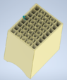
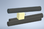
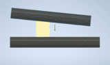
Specifically, I need advice on how to approach analyzing a box filled with ribs. What calculations should I prioritize? The box is intended to support a pipe with a weight of approximately 480 kg per meter in smaller increments at a time, acting as a sort of intermediate storage. Thus, it will be subjected to roughly 30,000 N of total force, with forces primarily in the Y-direction and support along the side walls in the X-direction due to high friction, assuming it's stationary (fixed).

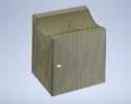
The material I've chosen is Nylon66, as in Inventor, with dimensions of 15mm for the outer walls and upper section, and 5mm for the ribs. I'm also considering simplified calculations where appropriate. Any tips on confirming these calculations? Considerations for buckling, bulging, moment, von Mises stresses, etc.?

Appreciate any help I can get.
 

Attachments

  • Bilde 4.png
    Bilde 4.png
    44.6 KB · Views: 74
  • Bilde 3.png
    Bilde 3.png
    61.1 KB · Views: 65
  • Bilde 2.png
    Bilde 2.png
    41.3 KB · Views: 80
  • Bilde 1.png
    Bilde 1.png
    110.9 KB · Views: 75
Last edited by a moderator:
Engineering news on Phys.org
NNM said:
Specifically, I need advice on how to approach analyzing a box filled with ribs.
Your question raises a few questions. You mention composite materials and Nylon 66. Which is it? Is it a fiber reinforced Nylon 66 or pure Nylon? If pure Nylon, that's a plastic, not a composite.

You mention friction, or are you trying to say that the sides are confined? Friction is very difficult to model properly, while confining the sides is easy to model.

Detailed manual calculations of your structure are unrealistic. The realistic manual calculation is a simple P/A for the portion of the structure that is in contact with the pipe, combined with a sufficient safety factor. Your Image 1 shows a structure with a saddle for the pipe, while your Image 4 shows a simple rectangular block structure. Which is it? Is the pipe laying flat on the structure, or is it at an angle as indicated in your Image 2?

What is the criteria for a good design? Is it a failure if the structure deflects elastically by 0.01 mm, or is it a failure only if it collapses completely?
 
Being pipes, they may be carrying fluids at relative high velocities, which induce strong lateral forces on any support when pipes are changing direction and dilatating-contracting under changes of temperature.
Please, consider that additional load for designing anchoring of the blocks to either pipes or ground, footings, etc.
 
jrmichler said:
Your question raises a few questions. You mention composite materials and Nylon 66. Which is it? Is it a fiber reinforced Nylon 66 or pure Nylon? If pure Nylon, that's a plastic, not a composite.

You mention friction, or are you trying to say that the sides are confined? Friction is very difficult to model properly, while confining the sides is easy to model.

Detailed manual calculations of your structure are unrealistic. The realistic manual calculation is a simple P/A for the portion of the structure that is in contact with the pipe, combined with a sufficient safety factor. Your Image 1 shows a structure with a saddle for the pipe, while your Image 4 shows a simple rectangular block structure. Which is it? Is the pipe laying flat on the structure, or is it at an angle as indicated in your Image 2?

What is the criteria for a good design? Is it a failure if the structure deflects elastically by 0.01 mm, or is it a failure only if it collapses completely?
The idea is that the construction should indeed be rounded to achieve an evenly distributed load. The images are somewhat unrealistic in terms of the lengths of the pipes. The product is intended to hold the pipes for only up to 1 minute during the movement of pipes in production. Therefore, the product is only meant to hold the pipe at a certain height to attach another tool before moving. The material is somewhat uncertain, but fiber-reinforced Nylon 6 is being considered, as well as regular Nylon. PP is also being considered. In a simple P/A calculation, is it the cross-sectional area of a region, or the full area of the structure of the delimited region? The criterion is that it should be able to operate and minimize the time used to move the pipe, so if it bends elastically, it doesn't matter much as long as it doesn't collapse for safety reasons
 
Posted June 2024 - 15 years after starting this class. I have learned a whole lot. To get to the short course on making your stock car, late model, hobby stock E-mod handle, look at the index below. Read all posts on Roll Center, Jacking effect and Why does car drive straight to the wall when I gas it? Also read You really have two race cars. This will cover 90% of problems you have. Simply put, the car pushes going in and is loose coming out. You do not have enuff downforce on the right...
I'm trying to decide what size and type of galvanized steel I need for 2 cantilever extensions. The cantilever is 5 ft. The space between the two cantilever arms is a 17 ft Gap the center 7 ft of the 17 ft Gap we'll need to Bear approximately 17,000 lb spread evenly from the front of the cantilever to the back of the cantilever over 5 ft. I will put support beams across these cantilever arms to support the load evenly
Thread 'What's the most likely cause for this carbon seal crack?'
We have a molded carbon graphite seal that is used in an inline axial piston, variable displacement hydraulic pump. One of our customers reported that, when using the “A” parts in the past, they only needed to replace them due to normal wear. However, after switching to our parts, the replacement cycle seems to be much shorter due to “broken” or “cracked” failures. This issue was identified after hydraulic fluid leakage was observed. According to their records, the same problem has occurred...
Back
Top