Simulation of load-unload test in Abaqus

  • Thread starter Thread starter Faezeh
  • Start date Start date
  • Tags Tags
    Abaqus Simulation
AI Thread Summary
The discussion focuses on simulating a load-unload test in Abaqus, where the user encounters unexpected negative forces and stresses in their model, despite expecting all values to be positive. The issue is attributed to the definition of displacement boundary conditions using amplitude, which can cause stress to overshoot into negative values. A suggested solution includes increasing the resolution of the loading amplitude by adding more points, thereby refining the increment. Additionally, starting with a simpler model, such as a single hex element, is recommended to troubleshoot the problem. Properly adjusting the model settings and verifying results are crucial for accurate simulations.
Faezeh
Messages
1
Reaction score
0
Hello,

I am trying to simulate the load-unload test in Abaqus under the following loading schedule using my UMAT (which has already been validated).
Picture1.jpg

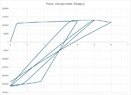
As you see, the load-unload test is pure tensile with positive displacements; however as I modelled it in Abaqus the force-displacement curve as well as the stress-strain curves give me some negative forces (stresses), while theoretically all the stresses and strains should be positive. Here is the numerical load-displacement curve which is obtained from Abaqus:
View attachment 343408
This is the experimental result (Stress-strain):

Picture5.jpg

As you see there shouldn't be any negative forces (stresses) in the model. I don't know what is the problem with the model. it should be noted that I tried the model which is in this YouTube video ()
 

Attachments

  • Picture4.jpg
    Picture4.jpg
    38.8 KB · Views: 49
Engineering news on Phys.org
Hi,

I have encountered this issue in my cyclic loading tensile test simulation but only my stresses were negative. This usually occurs when you have defined a displacement boundary condition using amplitude to replicate the loading. Since we implement a defined displacement at a defined time step/increment, the stress tends to "overshoot" into the negative region to compensate for this definition as well as calculations done for the material by Abaqus.

I fixed it by increasing the resolution of the amplitude of loading i.e., more points in the amplitude (increasing increment from 0.001 to 0.0001 for example)

Also, I am unable to see your Abaqus result.

Hope this helps. Good luck.
 
Posted June 2024 - 15 years after starting this class. I have learned a whole lot. To get to the short course on making your stock car, late model, hobby stock E-mod handle, look at the index below. Read all posts on Roll Center, Jacking effect and Why does car drive straight to the wall when I gas it? Also read You really have two race cars. This will cover 90% of problems you have. Simply put, the car pushes going in and is loose coming out. You do not have enuff downforce on the right...
I'm trying to decide what size and type of galvanized steel I need for 2 cantilever extensions. The cantilever is 5 ft. The space between the two cantilever arms is a 17 ft Gap the center 7 ft of the 17 ft Gap we'll need to Bear approximately 17,000 lb spread evenly from the front of the cantilever to the back of the cantilever over 5 ft. I will put support beams across these cantilever arms to support the load evenly
Thread 'What's the most likely cause for this carbon seal crack?'
We have a molded carbon graphite seal that is used in an inline axial piston, variable displacement hydraulic pump. One of our customers reported that, when using the “A” parts in the past, they only needed to replace them due to normal wear. However, after switching to our parts, the replacement cycle seems to be much shorter due to “broken” or “cracked” failures. This issue was identified after hydraulic fluid leakage was observed. According to their records, the same problem has occurred...
Back
Top