mc_09
- 1
- 0
- TL;DR Summary
- Designing a parallelogram-mounted printhead that prints onto concrete. Adding a 6" polyurethane wheel to maintain a 0.25" gap and allow smooth movement. Looking for advice on how to prevent vibration/slamming when the wheel contacts the surface — considering springs or dampers, but open to better ideas. Need specific hardware recommendations and mounting tips.
I'm a design engineer, but admittedly not very experienced in mechanical systems. I'm currently working on a project where I need to add smooth, soft movement to a parallelogram mount that supports a printhead. I could really use some guidance from more mechanically savvy folks.
Project Overview:
What I need help with:
1. Stabilizing the Mechanism:
2. Ideas I'm Considering:
Please provide specific hardware suggestions – part numbers, Amazon/McMaster-Carr links, or product names.
I've labeled all the parts (A–E) for easier reference in the comments/discussion.
Thanks in advance! Happy to provide sketches or more details if needed.
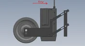
EDIT: I uploaded a back side image a bit more refined
Project Overview:
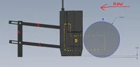
- The printhead is mounted to a parallelogram-style arm and will be printing downward onto a sheet of concrete
- I'm planning to add a 6" diameter polyurethane wheel (labeled Part E in blue) to allow for a smooth transition as the printhead engages with the concrete surface
- The wheel should keep a consistent 0.25" gap between the printhead and the top of the concrete.
- The wheel will likely be mounted using an adapter plate (Part D in yellow), which connects to the back of the printhead and also supports the wheel
What I need help with:
1. Stabilizing the Mechanism:
- When the wheel hits the concrete and lifts the printhead, I want to avoid any rattling or vibration in the mounting.
- I'm worried about the printhead "slamming down" if the joints are loosened to allow adjustability.
- Ideally, I want some form of damping or soft control when the wheel engages with the concrete
2. Ideas I'm Considering:
- I was thinking of adding springs to absorb shock and provide controlled lift/drop but I’m unsure where to mount them or if this is the best option.
- Open to alternative suggestions
Please provide specific hardware suggestions – part numbers, Amazon/McMaster-Carr links, or product names.
I've labeled all the parts (A–E) for easier reference in the comments/discussion.
Thanks in advance! Happy to provide sketches or more details if needed.
EDIT: I uploaded a back side image a bit more refined
Attachments
Last edited: