Solving MOSFET Circuit Problem with Q1 & Q2

  • Thread starter Thread starter etf
  • Start date Start date
  • Tags Tags
    Circuit Mosfet
Join the discussion
Registration is free. Ask a follow-up in this thread, or start your own.
5 replies · 4K views
etf
Messages
179
Reaction score
2
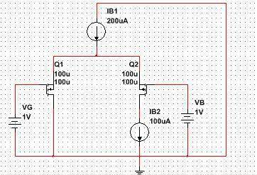
Here is my circuit:

kolo.JPG


Q1 is NMOS and Q2 is PMOS.
Q1: VT1=0.7V, beta1=2mA/V^2
Q2: VT2=-0.9V, beta2=1.8mA/V^2.
I assumed that both transistors work in saturation. In this mode it must be:
Q1: VG1S1 > VT1, VG1D1 < VT1, ID1=beta1*(VG1S1-VT1)^2/2,
Q2: VS2G2 > -VT2, VD2G2 < -VT2, ID2=beta2*(VS2G2+VT2)^2/2.

We see on scheme that ID2=IB2. Using KCL we get ID1=IB1-ID2=100uA.
Using KVL we get VG1S1=VG. If we put VG1S1=VG in our equation for drain's current in saturation mode we get that ID1=9*10^(-5) A so our equation doesn't hold? (ID1=IB1-ID2=100uA.) :confused:
 
Last edited:
Engineering news on Phys.org
I am confused.
Q1 is a voltage follower that sets the voltage to the common source and 200uA current source.
Q2 can only have 100uA current sink.
Q1 current must carry the difference which is –100 uA, (backwards).
But Q2 is controlled by VB between the drain and gate, not the source.

You have specified voltages and currents and the V~I relationships.
There is no degree of freedom, so you have an over-specified contradiction.

Can you produce a circuit diagram that shows the circuit you are modelling, as it would be implemented between supply rails. That should identify the contradiction.
 
  • Like
Likes   Reactions: 1 person
This is example from my textbook. Here is complete text and original scheme:
Find modes of operation of MOSFETs, their Q points, output DC voltage and voltage gain Av. VG=1V, Vt1=0.7V, Vt2=-0.9V, VA1=VA2=20V, beta1=2mA/V^2, beta2=1.8mA/V^2, IB1=200uA, IB2=100uA, VB=1V.

You can see solution below "Rezultat".
 

Attachments

  • 24052014886.jpg
    24052014886.jpg
    31.6 KB · Views: 627
Last edited:
MOSFET circuit contradiction

Just to mention that NI Multisim 13.0 refuses to simulate original circuit, but if I put VG=1.0162V (100*10^-6 approximately equals 2*10^(-3)*(1.0162-0.7)^2/2 so relation ID1=beta1*(VG1S1-VT1)^2/2 is satisfied) instead of Vg=1V Multisim simulates circuit.
 
Last edited:
Since there are finite Early voltages (VA1=VA2=20V) I must include these voltages in drain's currents like this:
ID1=(beta1/2)*((VG1S1-VT1)^2)*(1+lambda*VD1S1),
ID2=(beta2/2)*((VS2G2+VT2)^2)*(1+lambda*VS1D1),
where lambda is coefficient of channel modulation, lambda=1/VA.
 
You show as a "folded cascode" amplifier (CS + CG).
First what you need is to use this equation
Id1 = 0.5*β*(Vgs1 + Vt1)^2 * (1 + λ*Vds1) and solve is for Vds1.
Because from inspection we know that Vgs1 = 1V and Id1 = 100μA.
After we solve this we get Vds1 = 2.22222V. Thanks to this we can find Vgs2 and solve for Vsd2.
Vgs2 = - 1.22222V and Vsd2 = 1.40309V

And Vout = Vds1 - Vsd2 = 2.22222V - 1.40309V = 0.81913V

And simulation (LTspice) shows similar result.

Edit... And your multisim digram is completely wrong. Q1 is upside down and you have no VDD source.
 

Attachments

  • ff.PNG
    ff.PNG
    4.9 KB · Views: 638
Last edited:
  • Like
Likes   Reactions: 1 person