nauman
- 98
- 5
- TL;DR
- Calculations of Source Level of Cylindrical Array of multiple transducers with each transducer with known Transmit Voltage Response 'TVR'
Hi all
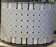
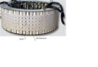
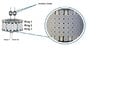
I am trying to calculate Source Level 'SL' of a underwater acoustic Cylindrical Array with multiple Transducers. The array has 03 Rings with 32 transducers in each Ring. The spacing between each ring is around 0.18m whereas Dia of each Ring is about 1m. Each transducer is being driven with separate Power Amplifier.
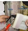
What i know about SL of individual transducer is that if we apply Vrms to a transducer having a 'TVR' of X dB, transducer SL will be calculated as:
SL = 20LOG10(Vrms)+X dB
On the basis of this SL calculations, I want to know how can we calculate 'SL' of complete cylindrical array (32x3 elements) in 'Omni Directional' Mode if we know TVR and Vrms applied to each Transducer? Here 'Omni Directional' means same level of transmission in all directions simultaneously.
Thanks
I am trying to calculate Source Level 'SL' of a underwater acoustic Cylindrical Array with multiple Transducers. The array has 03 Rings with 32 transducers in each Ring. The spacing between each ring is around 0.18m whereas Dia of each Ring is about 1m. Each transducer is being driven with separate Power Amplifier.
What i know about SL of individual transducer is that if we apply Vrms to a transducer having a 'TVR' of X dB, transducer SL will be calculated as:
SL = 20LOG10(Vrms)+X dB
On the basis of this SL calculations, I want to know how can we calculate 'SL' of complete cylindrical array (32x3 elements) in 'Omni Directional' Mode if we know TVR and Vrms applied to each Transducer? Here 'Omni Directional' means same level of transmission in all directions simultaneously.
Thanks