The choice of sweep angle (low speed) and its impact on C_L, C_D, C_M

In summary, the group project is to design a powered model flying wing that can fly for as long as possible. Wing sweep is a necessary design feature to create lift, but the airfoil with reflex cannot create enough lift. The stability comes from flying slightly sideways, when one wing appears to become longer with a shorter chord, while the other becomes shorter with a longer chord. The surface area of the wing remains constant, but the lift and drag stabilise the orientation of the wing to the direction of flight. Propellers are mounted below or behind the wing, and the orientation control surfaces are in the propeller-stream, so directional control is possible when on the ground or flying just above stall speed. The mass of the motors will determine
  • #1
Leo Liu
353
156
My school's group project is to design a powered model flying wing that can fly for as long as possible. To make it stable in the longitudinal direction, we either have to use a swept wing design or an airfoil with reflex (like BR1). We are forced to use wing sweep because the airfoil with reflex cannot create enough lift.

A rule of thumb I found for the sweep angle is about ##20^\circ## for a model flying wing. I am not sure if it is optimal and am keen to know if there is a way to treat this topic more rigorously.

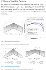
I did some research and was not able to find a rule-of-thumb formula for ##C_L##, ##C_D##, and ##C_M##. The closest thing I can find is this research.
1669675807878.png

I am wondering if such a formula exists, and if not, how we should estimate the changes in the three coefficients. Do we just apply a guessed margin and call it a day?

Another question I would like to ask is what are the factors and influences we need to consider when deciding the locations to mount the motors and propellers. Would it be more beneficial to put them at the leading edge or at the trailing edge?

The initial design of our flying wing:
Screenshot 2022-11-28 at 11.55.35 PM.png


Your input will be highly appreciated. Have a good one!
 

Attachments

  • 1669676197719.png
    1669676197719.png
    30.5 KB · Views: 107
Last edited:
Physics news on Phys.org
  • #2
Leo Liu said:
I am wondering if such a formula exist, and if not, how we should estimate the changes in the three coefficients.
The stability comes from flying slightly sideways, when one wing appears to become longer with a shorter chord, while the other becomes shorter with a longer chord. The surface area of the wing remains constant, but the lift and drag stabilise the orientation of the wing to the direction of flight.

Leo Liu said:
Another question I would like to ask is what are the factors and influences we need to consider when deciding the locations to mount the motors and propellers. Would it be more beneficial to put them at the leading edge or at the trailing edge?
Avoid disturbing airflow over the upper surface of the wing, which is where most of the lift is found. That suggests mounting the propeller below and/or behind the wing. Make sure the orientation control surfaces (equivalent tail) are in the propeller-stream, so you will have directional control when on the ground, or when flying at just above stall speed.
The mass of the motors will determine CofM. The aircraft should be stable in glide, so mounting engines near the centre of the wing is preferred, but not ideal. A longer prop drive shaft is a possibility.
 
  • Informative
Likes Leo Liu
  • #3
Thanks for the answers.
Baluncore said:
The stability comes from flying slightly sideways, when one wing appears to become longer with a shorter chord, while the other becomes shorter with a longer chord. The surface area of the wing remains constant, but the lift and drag stabilise the orientation of the wing to the direction of flight.
By stability I actually meant longitudinal stability rather than directional. From my understanding the wing sweep shifts the lift behind the CoM, but I don't quite understand how this works without reflex which creates a positive moment about the aerodynamic center. Simulation indicates stability for the design with NACA2412. (We also came up with a hybrid design involving both types of airfoils to get the advantages of both, but the lift performance is worse than NACA2412.)
Screenshot 2022-11-29 at 12.36.59 AM.png


Baluncore said:
The mass of the motors will determine CofM. The aircraft should be stable in glide, so mounting engines near the centre of the wing is preferred, but not ideal. A longer prop drive shaft is a possibility.
Sorry by center do you mean the aerodynamic center or CoM? And why does mounting the engines near the center of the wing ensure that the plane glides well?
 
  • #4
Following loss of power, you need to recover the craft by gliding. The aerodynamic balance at a stable low-speed glide should be optimised. Under power or in a fast glide, you will have energy to waste and a faster airflow over the control surfaces, so efficiency is not critical. (You are not designing this craft for long haul passenger transport).

If you mount the engines towards the rear, with pusher props, you must then add mass up front to counter the moment about the aerodynamic centre. That added mass is a waste of good lift if you can avoid ballast.

You have not identified the type of engine, electric or liquid fuel.

Stability is improved if longitudinal inertia is increased, if the mass can be distributed towards the ends of a longer body. Engines at the back with batteries up front might work, but since the mass of fuel is changing during the flight, fuel tanks must be in a neutral position in the wing. That explains why heavy engines are hung below the wing in many aircraft.
 
  • Like
Likes Leo Liu
  • #5
Baluncore said:
Following loss of power, you need to recover the craft by gliding.
If the flights of our model plane are designed to be powered throughout, will it change the requirement here? We don't want to waste energy by making the plane climbing up.
Baluncore said:
You have not identified the type of engine, electric or liquid fuel.
The wingspan is a mere 600mm so we can only use two coreless DC motors to power the flying wing.
Baluncore said:
Engines at the back with batteries up front might work, but since the mass of fuel is changing during the flight, fuel tanks must be in a neutral position in the wing.
Hmmmm our plane will use a battery. I assume I can place it at the front as a counterweight?
 
  • #6
Leo Liu said:
our plane will use a battery. I assume I can place it at the front as a counterweight?
Yes. A battery will make a good counterweight.
The two motors can be spaced apart, at the trailing edge. If they are far apart they will provide directional control, and some stabilising inertia.

Contemplate having two counter-rotating pusher propellers, one in each wing tip vortex. That way, you might recover some of the induced drag as thrust.
 
  • Like
Likes Leo Liu

1. What is the sweep angle and why is it important in aircraft design?

The sweep angle is the angle between the wing's leading edge and a line perpendicular to the longitudinal axis of the aircraft. It is important in aircraft design because it affects the aerodynamic performance of the wing, including lift, drag, and moment coefficients.

2. How does the sweep angle impact the lift coefficient (C_L) of an aircraft?

The sweep angle influences the lift coefficient by changing the effective angle of attack of the wing. At low speeds, a higher sweep angle can increase the lift coefficient by creating a more favorable pressure distribution on the wing surface.

3. Does the sweep angle have an effect on the drag coefficient (C_D) of an aircraft?

Yes, the sweep angle can impact the drag coefficient of an aircraft. A higher sweep angle can reduce drag by decreasing the amount of air that flows over the wing's surface and creating less drag-inducing vortices.

4. How does the choice of sweep angle affect the moment coefficient (C_M) of an aircraft?

The sweep angle can have a significant impact on the moment coefficient, which is a measure of the aircraft's stability. A higher sweep angle can lead to a more stable aircraft by shifting the center of pressure aft, while a lower sweep angle can result in a less stable aircraft.

5. What factors should be considered when selecting the sweep angle for an aircraft's design?

When choosing the sweep angle for an aircraft, factors such as the desired lift and drag characteristics, stability requirements, and structural constraints must be taken into account. The aircraft's intended speed and purpose will also play a role in determining the most suitable sweep angle for optimal performance.

Similar threads

Replies
1
Views
2K
  • Mechanics
Replies
7
Views
2K
  • Other Physics Topics
Replies
11
Views
8K
  • Mechanical Engineering
Replies
2
Views
7K
  • Classical Physics
Replies
10
Views
4K
  • General Engineering
Replies
27
Views
8K
Back
Top