Thread No-Go plug gage allows 3 turns to enter. That's too many!

  • Thread starter Thread starter DTM
  • Start date Start date
AI Thread Summary
The discussion centers on the ASME B1.2 standard, which allows a no-go plug gage to enter an internal thread up to three complete turns. Concerns are raised about this allowance, particularly for critical nuts with limited thread engagement, as it could lead to inadequate fastening strength. Users express frustration over the potential for loose fittings and the implications of the standard on their engineering calculations. There is a suggestion to limit the acceptable turns to 1.5 to 2 turns for better quality control. The conversation highlights the confusion stemming from evolving standards and the need for manufacturers to consider tighter specifications to ensure thread integrity.
DTM
Messages
75
Reaction score
9
After over 25 years of engineering, designing and analyzing bolted joints, I just learned this little fact. According to ASME B1.2, Gages and Gaging for Unified Inch Screw Threads:
"The no-go gage should not pass over more than three complete turns when inserted into the internal thread of the product. "

3 turns seems like way to much. I have some really critical nuts that are of standard geometry (5/8"-11 UNC 3B) and have about 4.5 threads when you account for the chamfers on either end. So this is saying that 2/3 of my threads could be drilled out to nearly the major diameter, leaving me with only 1/3 the thread engagement I expected, and that's an acceptable nut? That's not how I've been calculating my thread engagement.

We got a batch of nuts that our No-Go plug gages goes in between 2.5 and 3.5 turns on different pieces. It's totally loose for the first couple of turns. The fastener vendor is saying this is acceptable and according to ASME B1.2, for at least the ones with less than 3 turns, he may be right.

I'm I going to have to put notes on all my prints calling out no more than 1.5 turns of a no-go plug gage may enter the part?
Has anyone else dealt with this? Any suggestions of a different spec we should consider calling out?
 
Engineering news on Phys.org
As with all things Government is involved with, confusion.
The Old ANSI standard was 1 1/2 turns. two turns Max. Then the newer standard permitted 3 turn maximum and NO FORCE.
My guess is the manufacturer did not like the high scrap rate caused by 1 1/2 turns.

Read the link below for traditional old style GO NO GO thread plug gages.

https://www.threadcheck.com/how-to-...EednjlJu-VCHoxOETG0leU0mcj6PXnJIMzRN9DFuEI9C_

The go thread plug gage should engage the internal threaded part with very little force used. The engagement should be smooth. There is no specification regarding torque or pounds of pressure for using thread plug gages. Common sense should be applied based on factors of thread size, pitch, and application. If the gage starts to bind, the inspector should stop before damaging the part or the gage. The part may be undersized or tapered. Other possibilities include lead error or a damaged thread. With fine threads the inspector should be careful to not cross thread the parts.


It is important to use the no go gage as it checks pitch diameter exclusively. It is unaffected by other conditions in the screw thread as it is intentionally truncated on the crests and with greater clearance applied on the roots of the thread. The no go thread plug should not enter the part more than 3 turns although in practice it is advisable to limit the amount of turns to 1 ½ - 2 turns max. The user just simply counts turns. The end user should review the applicable thread specification in detail as there are variations to the above practice.


As stated in ANSI/ASME B1.2-1983, the “NoGo (Lo) functional diameter is acceptable when the NoGo (Lo) thread ring gage applied to the product external thread does not pass over the thread more than three complete turns.” The gage should not be forced. Special consideration such as exceptionally thin or ductile material, small number of threads, etc., may require modification of accepting up to 3 turns of the gage. It is highly recommended that a manufacturer not allow a maximum of 3 turns during thread fabrication as every thread ring gage is set slightly different to due the gage maker tolerances of set plugs and the subjective nature of setting adjustable style thread ring gages.

Below - from Inspection and Gaging - Kennedy- Hoffman- Bond, page 470 but ref. is ANSI B1.1 Unified Screw Threads " The "No Go" end must not enter more than 1 1/2 turns, else the tapped hole is too large.
ANSI/ASME B1.2-1983 revised per above verbiage
RM
 

Attachments

  • thrd 1_000016.webp
    thrd 1_000016.webp
    38.7 KB · Views: 2
Last edited:
  • Informative
  • Like
Likes DTM, DaveE and berkeman
Official wording in ANSI / AMSE B1.2

"NOT GO (HI) functional diameter is acceptable when the NOT GO (HI) thread plug gage applied to the product internal thread does not enter more than three complete turns. The gage should not be forced. Special requirements such as exceptionally thin or ductile material, small number of threads, etc., may necessitate modification of this practice. "
 
Thanks everyone for the replies. So it sounds like the only spec we know, ANSI/ASME B1.2 states that the NOT GO (Hi) thread plug gage may not enter more than 3 complete turns. My question to any of you reading this post is:
HOW DOES THIS MAKE ANY SENSE?

The common rule of thumb for fasteners is to have a thread engagement of ~ 1 times the nominal diameter. So a 1/4-20 thread will have ~1/4" thread engagement or about 5 threads of engagement (1/4" * 20thds/").

So this spec, B1.2, says 3 of those threads can be oversized to the point of not engaging the NOT GO gage and therefore the mating part. So 3/5 of my threads may be nearly or totally useless. Obviously most thread manufactures don't make threads this bad, but I shouldn't need to specify on EVERY threaded part I design to inspect so the NOT GO gage should Not Go in more than 1 thread.

This standard could mean we have life protecting bolted joints out there that are less than 1/2 as strong as the designer intended.

I feel this is something that should be brought up with the ASME B1.2 standards group. Anyone know how to properly contact them? I'll look into it.
 
I haven't read the original specification, but the following might explain the three complete turns:

https://www.standardne.com/thread-engagement-an-important-detail/ said:
ASME B1.1 (Unified Inch Screw Threads) states that the last effective thread of an externally threaded fastener occurs about three threads from the end of the bolt or stud. So, a stud or bolt is not effectively joined with the nut until the stud or bolt extends at least three or more threads beyond the end of the nut.

I imagine this also applies to the NOGO gauge, i.e., the first three turns of the gauge are not expected to be to specification. Furthermore (emphasis mine):

https://www.threadcheck.com/no-go-gaging-per-ansi-asme-b1.2-1983-an-american-national-standard/technicalinfo/ said:
Thread plug gages when applied to the product internal thread may engage only the end threads (which may not be representative of the complete thread). Entering threads on product are incomplete and permit gages to start. Starting threads on NoGo (HI) plugs are subject to greater wear than the remaining threads. As Stated in ANSI/ASME B1.2-1983, the “NoGo (Hi) functional diameter is acceptable when the NoGo (Hi) thread plug gage applied to the product internal thread does not pass over the thread more than three complete turns.” The gage should not be forced. Special consideration such as exceptionally thin or ductile material, small number of threads, etc., may require modification of accepting up to 3 turns of the gage. It is highly recommended that a manufacturer not allow a maximum of 3 turns during thread fabrication as every thread plug gage may gauge differently due the actual size and gage maker tolerances allowed.
 
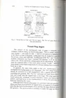
Go / No-Go gaging is direct and generally simple. If the Go fits (Fig. 1) and the No-Go does not (Fig. 2), the functional thread is in tolerance. The potential for problems occurs when the product begins to drift towards the extremes of the tolerance. This is when a better understanding of the gage design, tolerances and functions becomes critical.


Fig 1 2 G NG Thread plg


Per ASME B1.2-1983, the “Go thread plug gage must enter and pass through the full-threaded length of the product freely. The Go thread plug gage is a cumulative check of all thread elements except minor diameter.” The pitch diameter of the Go thread plug gage is the same as the minimum pitch diameter of the internal part thread with a plus tolerance. The Go thread plug gage major diameter is equal to the minimum major diameter of the internal part thread with a plus tolerance. The major diameter of the Go thread plug gage also represents or exceeds the max major diameter of the external mating thread. The minor diameter of the Go thread plug gage is a clearance feature. The only requirement is that the minor diameter of the Go thread plug gage is cleared beyond theoretical sharp. The purpose of the Go is to insure assembly with the mating external part. It does not measure the major or minor diameter of the internal thread. Simply put, the Go thread plug gage insures assembly with an in-tolerance external thread.


The No-Go thread plug gage only inspects the maximum functional pitch diameter of the internal part thread. The major and minor diameters of the No-Go thread plug gage are clearance dimensions. It is important to note that the major diameter of the No-Go thread plug gage is always smaller than the major diameter of the Go thread plug gage for 60° screw threads. This is done by design to insure that, if the No-Go gage fits into the internal part thread, it means that the internal part thread pitch diameter is oversize. A properly manufactured No-Go thread plug gage should never contact either the major or the minor diameter of the internal part thread.


No-Go acceptance rules generate most of the questions we receive on thread gages. Both the ASME B1.2 and the ASME B1.16M have rules and stated exceptions for the number of turns a No-Go thread plug gage may enter the internal part thread. The ASME B1.2-1983 for UN Series Inch Screw Threads states the No-Go may enter up to three turns. The gages must not be forced. Other considerations that may necessitate a change to this practice are exceptionally thin or ductile material, small number of threads, etc. The M Series Metric Screw Threads per ASME B1.16M are different. The Metric threads only allow the No-Go thread plug gage to enter up to two turns with the same exceptions as the Unified Inch Screw Threads. The purpose of this allowance is to take into account the incomplete thread on the part and additional wear on the starting threads on the No-Go Thread plug gage.


What does it mean when the Go does not enter the internal part thread? This would indicate that the functional thread is undersize or too small. Many times this means that the internal part thread is undersize at the pitch diameter or at the major diameter. It may also indicate a problem with the thread form or the lead of the thread. When this happens, a review of the thread cutting or forming tool geometry should occur. The manner in which the internal part thread is manufactured or the materials used may have an impact on the possible causes.


Fig 3 4 G NG Thread plg


When the No-Go enters the internal part thread, the pitch diameter is oversize. Confusion occurs when the operator makes the thread and the Go does not enter (Fig. 3) and the No-Go does (Fig. 4). In many machining operations, when the Go does not enter, the operators makes small incremental changes in the cutting tools or depth of cut until the Go thread plug gage passes freely through the entire length of the internal thread. Once they hit the point where the Go enters, they then apply the No-Go. In theory, the No-Go should not enter. This indicates that they have a good internal part thread. When both the Go and No-Go do pass through the internal thread or the Go does not and the No-Go does enter, the understanding of the gage function will help solve the problem. Because the only feature on the Go thread plug gage that is larger than the No-Go thread plug is the major diameter, it is the first place to look. This problem usually indicates a worn cutting tool that has a major diameter that is undersize or is creating a radius in the root of the internal thread that is too large and interferes with the major diameter of the Go thread plug major diameter. Remember, not only does the major diameter of the Go thread plug represent the min major of the internal part, it also represents the max major diameter of the external mating part. The key is understanding what the design purpose of the gage is and how variations in the manufacture of the internal part thread affect the gaging results. Major diameter interference covers the largest percentage of these problems. It is not the only possible cause. Poor lead, or out of round threads can cause some of these issues as well.


Do not forget to measure the major diameter of external part threads and the minor diameter of internal part threads. The previously mentioned ASME standards list the sizes for cylindrical Class Z ring gages to inspect the external part thread major and cylindrical Class Z minor diameter check plug gages for internal part threads. Measuring these features on the part threads is critical to insuring assembly of the mating parts. Other major or minor diameter inspection tools with equal or better accuracy may be used as well.
Fig-1-2-G-NG-Thread-plg__ResizedImageWzg3MywyNDZd.webp
 

Attachments

  • 3_Wire_Measurement_of_Pitch_Dia.webp
    3_Wire_Measurement_of_Pitch_Dia.webp
    27.3 KB · Views: 1
Back
Top