Transform question about this circuit

  • Context: Engineering 
  • Thread starter Thread starter Fuji
  • Start date Start date
  • Tags Tags
    Circuit Transform
Join the discussion
Ask a follow-up here, or get your own question answered by working scientists, mathematicians and engineers — people, not an autocomplete.
Real named experts · corrections over time · the nuance an AI answer skips
4 replies · 2K views
Fuji
Messages
2
Reaction score
0
Homework Statement
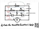
Need to derive the transfer function
Relevant Equations
G(s)=Vo(s)/Vi(s)
F.JPG
I Normally can solve these but when Vo is embeded into the circuit, is throwing me for a loop (no pun is intended). My question is, if I apply Kirchoff's voltage law: VR+VC+VL-Vi=0, I'm not quite sure how this would be set up when Vo is between R1R2 & C1C2?
I believe this ia 4 Loop circuit:
I1 = I2 + I3 + I4
I2 = [(Vin-Vout) / C1] + (Vout / C2)
I3 = [(Vin-Vout) / R1] + (Vout / R2)
I4 = Vin / L
Would this be correct for the assumption?
 
Last edited:
Physics news on Phys.org
Could you label where the currents are with arrows in your diagram? So basically label where the currents "I1", "I2", "I3", etc.. are actually going. That way anyone can get an idea of the directions (i.e. In/Out) you're thinking about.

I was going to suggest using a node voltage method but it seems like you're on a good track for this problem.

The first thing I would suggest is you convert all of the components into "impedances". At least for me, it would be easier to analyze the circuit that way.

So think back to what the equation for an inductor, capacitor, and resistor is. That way, you can convert everything into the "s" domain (or omega format, whichever one you want to call it). Then, from there, you can start writing out equations/relationships. See if things might even cancel out when solving for Vout/Vin.

We're not allowed to give "direct" answers to problems on here. I'm just trying to give you tips/advice on what steps to take or approaches to use.
 
Thanks for the input. I'm not looking for the answer, but if you check my work to see if I'm evaluating the problem correctly so far. I ended up changing this to a 3 loop circuit. It's not finished since I haven't derived the transfer function yet but before I go any furthur, I was wonder what I have is correct. The attached pdf has six pages to it.
 

Attachments

Last edited:
If Z2(s)=C1*C2/(C1+C2)*s ;Z3=R1+R2 ;Z4=1/L/s

Then, in my opinion, since Vi/s=Z2(s)*I2(s)=Z3(s)*I3(s)=Z4(s)*I4(s)

I2(s)=Vi/s/(C1*C2)*(C1+C2)/s=Vi/s^2*(C1+C2)/(C1*C2)

I3(s)=Vi/s/(R1+R2)

I3(s)*R1+Vo-I2/C1/s=0

Vo=I2(s)/C1/s-I3(s)*R1
 

Attachments

  • Transfer Function Gs.jpg
    Transfer Function Gs.jpg
    48.9 KB · Views: 161
Fuji, the first thing to do is get rid of L. Since Vi is a voltage source, all L does is draw some current from Vi, but it has no effect on Vo.

R1 and R2 form a voltage divider across Vi, and C1 and C2 do the same thing.

Let the right hand terminal of Vi be ground (reference node), and calculate the voltage across R2 using the voltage divider formula; that will be the voltage at the top of Vo. Calculate the voltage across C2 using the voltage divider formula; that will be the voltage at the bottom of Vo. The value of Vo will be the difference of the voltage across R2 and the voltage across C2.
 
Reply
  • Like
Likes   Reactions: Babadag