Troubleshooting LM311P Output Issue - Tips and Suggestions

  • Thread starter Thread starter Stonestreecty
  • Start date Start date
  • Tags Tags
    Amplifier
AI Thread Summary
The LM311P is exhibiting unexpected behavior, with the emitter output still sinking and sourcing current despite being unconnected. Current measurements show 14 mA when sinking at the collector but none when sourcing, not following the input signal. Suggestions include grounding the emitter output, using a pull-up resistor on the collector, and measuring the output voltage. It's important to check the input voltages to ensure they are within the common mode range, as this can affect performance. Properly diagnosing these issues is crucial for the circuit to function correctly.
Stonestreecty
Messages
20
Reaction score
3
TL;DR Summary
I'm using a LM311P. It is has a collector/emitter output. Because my circuit didn't function the way it should, I started debugging. But not following the input signal.
Hello, all
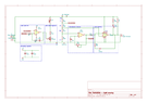
For this little project, I'm using a LM311P. It is has a collector/emitter output. Because my circuit didn't function the way it should, I started debugging.
With the collector unconnected the emitter (pin 1) still sinks (11 mA) and sources (20 mA) current, when applying a square wave input. I measured mean dc amperage to either rail, so the max is higher. I cannot explain this behavior.
Doing the current measurement on the collector (pin 7) with an unconnected emitter I get 14 mA when sinking, and none when sourcing. But not following the input signal.

Any suggestions what could cause this?
 

Attachments

  • schematic diagram.png
    schematic diagram.png
    19.5 KB · Views: 131
Engineering news on Phys.org
Stonestreecty said:
Summary:: I'm using a LM311P. It is has a collector/emitter output. Because my circuit didn't function the way it should, I started debugging. But not following the input signal.

With the collector unconnected the emitter (pin 1) still sinks (11 mA) and sources (20 mA) current, when applying a square wave input. I measured mean dc amperage to either rail, so the max is higher. I cannot explain this behavior.
The output is designed to be used as a voltage output that drives a load.
If you measure the output current you are testing the output current limiting.
Ground the emitter output, pullup the collector without the LED using a resistor to +5V, measure the output voltage on the collector.
Check the voltage needed by the LED. I cannot read the circuit text.
Check the input voltages and verify they are both in the common mode range. Some input structures invert when one input goes out of CM range.
 
Thread 'Weird near-field phenomenon I get in my EM simulation'
I recently made a basic simulation of wire antennas and I am not sure if the near field in my simulation is modeled correctly. One of the things that worry me is the fact that sometimes I see in my simulation "movements" in the near field that seems to be faster than the speed of wave propagation I defined (the speed of light in the simulation). Specifically I see "nodes" of low amplitude in the E field that are quickly "emitted" from the antenna and then slow down as they approach the far...
Hello dear reader, a brief introduction: Some 4 years ago someone started developing health related issues, apparently due to exposure to RF & ELF related frequencies and/or fields (Magnetic). This is currently becoming known as EHS. (Electromagnetic hypersensitivity is a claimed sensitivity to electromagnetic fields, to which adverse symptoms are attributed.) She experiences a deep burning sensation throughout her entire body, leaving her in pain and exhausted after a pulse has occurred...

Similar threads

Back
Top