tempneff
- 82
- 3
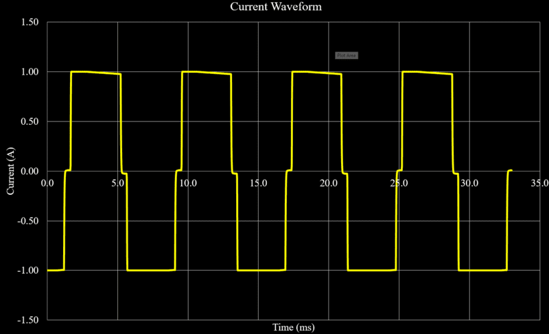
I hoped to use a Keithley 2400 source meter to generate a ~120Hz AC signal by outputting a 2-point sweep from 1A to -1A on an infinite trigger. The waveform image is attached below.
The end goal is a resistance measurement for bulk semiconductor materials, we prefer AC measurement to avoid thermoelectric drifts. To validate my input current I am measuring AC amperage through a verified 1.01 ohm resistor with a Keithley 2000-20 multimeter.
The meter measures .94A AC during the sweep. If I send 1A without sweeping and read DC current, it measures 1.01A; as expected.
I'd like to better understand the difference in magnitude. How is the measurement impacted by an "AC" current. Is there something problematic math-wise by not sending a sine wave.
The end goal is a resistance measurement for bulk semiconductor materials, we prefer AC measurement to avoid thermoelectric drifts. To validate my input current I am measuring AC amperage through a verified 1.01 ohm resistor with a Keithley 2000-20 multimeter.
The meter measures .94A AC during the sweep. If I send 1A without sweeping and read DC current, it measures 1.01A; as expected.
I'd like to better understand the difference in magnitude. How is the measurement impacted by an "AC" current. Is there something problematic math-wise by not sending a sine wave.
Attachments
