Discussion Overview
The discussion revolves around the inability to sense photocurrent in a short circuit geometry involving a photodiode or photovoltaic (PV) material. Participants explore the implications of circuit design, internal resistance, and measurement techniques in the context of experimental setups.
Discussion Character
- Exploratory
- Technical explanation
- Debate/contested
- Experimental/applied
Main Points Raised
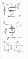
- One participant questions why a shorted circuit geometry does not sense photocurrent, suggesting that Kirchhoff's Law should apply.
- Another participant points out the role of internal resistance in the photodiode, explaining that most voltage appears across this resistance, leading to minimal current through the ammeter.
- Some participants express confusion about circuit representation and seek guidance on drawing the correct circuit geometry.
- A participant mentions measuring photovoltaic material and observing varying resistance values, which complicates the understanding of photocurrent sensing.
- There is a suggestion to test the setup with a simple LED to observe photocurrent, indicating potential issues with the DIY PV cell construction.
- Participants discuss the importance of the sensitivity of the ammeter and the potential need for a datasheet for the components used.
Areas of Agreement / Disagreement
Participants express differing views on the reasons for not sensing photocurrent, with some attributing it to internal resistance and others questioning the experimental setup. No consensus is reached on the underlying cause of the issue.
Contextual Notes
Participants mention limitations related to the sensitivity of measurement devices and the complexity of circuit representation, which may affect the understanding of the situation. There are also references to the internal resistance of components that are not fully resolved in the discussion.