Discussion Overview
The discussion revolves around the design and functionality of an H-bridge circuit using P-channel and N-channel MOSFETs, specifically addressing the configuration of bleed resistors and their impact on gate-source voltage (Vgs) protection for the MOSFETs. Participants explore the implications of their circuit design choices, including the use of transistors controlled by an Arduino to toggle the MOSFETs and the potential for current paths in the circuit.
Discussion Character
- Technical explanation
- Debate/contested
- Mathematical reasoning
Main Points Raised
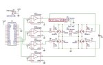
- One participant describes the layout of the H-bridge using two P-channel and two N-channel MOSFETs, detailing the connections and components involved, including bleed resistors and transistors.
- Another participant emphasizes the need to ensure that Q1 and Q3, as well as Q2 and Q4, are not on simultaneously, suggesting the use of identical FETs to create dead time.
- There is a proposal to use a 40V zener diode between the P-N gates or ~16V zeners across each Vgs with a current limiter, raising questions about the best approach for protecting the MOSFETs.
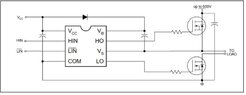
- One participant suggests that the circuit's simplicity is beneficial for understanding but warns that real-world applications may require more complexity and recommends consulting PMIC manufacturers for control chips.
- Another participant expresses uncertainty about the current path in the circuit, questioning whether the electric current would take the shortest path to ground through the bleed resistors.
- Clarifications are made regarding the toggling of inputs and the states of the MOSFETs when the input signals are low or high.
Areas of Agreement / Disagreement
Participants express differing views on the optimal configuration and protection methods for the MOSFETs, indicating that multiple competing approaches exist. The discussion remains unresolved regarding the best way to implement the circuit while ensuring the safety of the components.
Contextual Notes
Some participants mention specific voltage ratings and configurations, but there are unresolved assumptions about the behavior of the circuit under different conditions, including the impact of bleed resistors on current paths and Vgs levels.