Work done by a gas in a heat engine which compresses a spring

In summary, this experimental set-up is not going to do any work net work and it is not going to be useful to investigate about the aim of the research. However, if you want to use it to calculate the mechanical efficiency of a heat engine, you will need to change the orientation of the cylinder, and replace the spring with pebbles that you could add or remove from the piston at various elevations.
  • #1
Poorneshwar 2
11
0
TL;DR Summary
I have been looking at the heat engine concepts, and i'm a little confused. I have a experimental set-up which has a hot and cold sink, and a syringe where the gas inside expands and compresses when i switch between the sinks, and during the gas expansion, the syringe compresses a spring which compresses a spring. But, in this experiment, only understand that the isothermal processes takes place but how can i include the adiabatic processes so that it actually works like an actual heat engine.
Please, i need help
 
Physics news on Phys.org
  • #3
  • #4
Please provide a schematic diagram of your system.
 
  • Like
Likes Lord Jestocost
  • #5
Hello sir,

Thank you for your reply. I have attached the diagram below. Hope you could help me with this.
 

Attachments

  • IMG_0338.jpg
    IMG_0338.jpg
    30.8 KB · Views: 78
  • #6
The setup as you have it is not going to do any work net work. All it is going to do is compress the spring and then release the compression.
 
  • #7
Chestermiller said:
The setup as you have it is not going to do any work net work. All it is going to do is compress the spring and then release the compression.
Thank you for your reply again.

But is it possible that i can use this experimental set-up to calculate the mechanical efficiency of a heat engine. I think it is possible because i can calculate Qh, by using the formula for isothermal expansion and i can calculate Wext using the work done by the compression of the spring, which will allow me to calculate the mechanical efficiency of the engine. Is this possible?

If not is there any ways i can make this experimental set-up better. I really appreciate your help.
 
  • #8
I think that various practical realities will make your approach impractical. Try searching heat engine cycle diagram, and study some diagrams. Consider the assumptions behind those diagrams - friction, heat loss, flow loss, and more, are all assumed to have no effect on the analysis. That is why a real heat engine always has efficiency much lower than the theoretical efficiency. Then compare the losses of a real heat engine to your simplified model. Keep in mind that real heat engines do not operate on perfect isothermal or adiabatic processes, but somewhere in between. The difference in losses between a real heat engine and your model will be very large, so large that your measurements will not be useful in analyzing a real heat engine.

If you search Stirling engine kit, you will find many small, low cost heat engine kits. You would be better off to get one of these kits and analyze it. If you merely measure the hot and cold side temperatures, heat flow into the hot side, and power output, you will learn far more than you will learn from your simplified model.

BTW, the Amazon link from the above search is the following: https://www.amazon.com/STIRLING-ENGINE-KIT/s?k=STIRLING+ENGINE+KIT. The header says 206 results. Many of those should work for you.
 
  • Like
Likes russ_watters
  • #9
Yes, i understand what you're trying to explain here. But the aim of my research is "What effect does the temperature difference between the hot source and the cold sink have on the mechanical efficiency of a heat engine?" and i just want to mainly to use this set-up to understand how a heat engine works. Therefore, i can understand there are assumptions, but is there any way, where i can improve this experimental set-up to investigate about the aim of the research.

I have also looked at many PV diagrams for the processes of a heat engine cycle but in my experiment, i could see any clear adiabatic expansion or compression, but there was clear isothermal expansion, Qh and compression Qc, which i could use to calculate with the formulas. Even though, i do not get accurate results, i can evaluate all this in my evaluation. But, i just want to make sure, if this is the way a heat engine works.

Too add on, I have also checked the link you sent. I have also saw how they work, but how can i calculate the heat flow into the hot side, using that model and will i be able to change the temperature differences between the both sinks and see the effect on mechanical efficiency?

Thank you for your reply, it is very helpful.
 
  • #10
I would change the orientation of the cylinder to vertical, and replace the spring with pebbles that I could add or remove from the piston at various elevations.
 
  • #11
Yes, i tried this set-up before coming up with this. It didn’t seem to work because the syringe was a 100cc one and my school doesn’t have 10cc one which is suitable for this experiment. This didn’t make the air to expand in the syringe due it’s low pressure and it doesn’t have the power to lift the piston. That’s the reason why i switched to this set-up. I have attached the experimental set up i used below.

I hope you can give me a advice to continue with this experiment.
 

Attachments

  • AEAAB692-00CF-492F-81A5-85651D80A620.jpeg
    AEAAB692-00CF-492F-81A5-85651D80A620.jpeg
    24.9 KB · Views: 78
  • #12
Poorneshwar 2 said:
how can i calculate the heat flow into the hot side, using that model and will i be able to change the temperature differences between the both sinks and see the effect on mechanical efficiency?
You can heat the hot side using Nichrome wire. Amazon has a sample pack of Nichrome wire: https://www.amazon.com/dp/B07DGJKKSK/?tag=pfamazon01-20. And also high temperature ceramic insulation: https://www.amazon.com/dp/B07DGJKKSK/?tag=pfamazon01-20. Search Nichrome wire resistance to find how to calculate length and gauge to match a low voltage high current power supply.

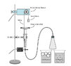
You need to wrap the Nichrome wire around the hot end, making sure to electrically insulate the wire from the heat engine, and each turn from the other turns. Then plenty of thermal insulation around the outside. Now you can accurately control the temperature and/or the heat input of the hot end.

Similarly, wrap some small diameter metal tubing around the cold end. Use a needle valve to control water flow in, thermometers to measure water input and output temperature, another thermometer to measure cold side temperature, and you can measure flow using a container and a watch. That will give you all of the information needed to measure heat flow out the cold side. Use a bucket of ice water if you want the cold side to be colder.

Power can be measured using a friction brake on the output shaft and a spring scale. Small heat engines work at low speed and low torque, so a friction brake can be as simple as two sticks and some rubber bands.

You would then have heat into the hot side, heat out the cold side, and output power. Everything you need to calculate mechanical efficiency, compare that to Carnot cycle efficiency, and some knowledge of the sources of inefficiency.

Poorneshwar 2 said:
I hope you can give me a advice to continue with this experiment.
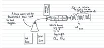
Calculate the amount of force that your range of temperatures can apply to the cylinder (syringe). Then measure the friction in the system by disconnecting the tube from the syringe. Add mass to the "small mass" until the syringe slowly moves one way, then remove mass until the syringe slowly moves the other way. The difference between the mass to move one way and the mass to move the other is the total friction of the syringe/motion sensor/pulley system.
 
  • #13
jrmichler said:
Similarly, wrap some small diameter metal tubing around the cold end. Use a needle valve to control water flow in, thermometers to measure water input and output temperature, another thermometer to measure cold side temperature, and you can measure flow using a container and a watch. That will give you all of the information needed to measure heat flow out the cold side. Use a bucket of ice water if you want the cold side to be colder.
thank you for the reply. It was v helpful for planning my experiment but i don’t understand why there will be water flow in and out in the experiment.

On the other hand, is there any other ways or a simpler, lesser complicated model than this to learn about how the heat engine works, by using material available in my lab, so that the set up is original.

Thank you again
 
  • #14
jrmichler said:
Calculate the amount of force that your range of temperatures can apply to the cylinder (syringe)
With regards to the first experimental set-up, so can i continue to with that set-up but just remove the spring and add a force meter, to detect the force by the expansion of the syringe, and does that force show the work done by the heat engine? If so, how can i calculate Qh of that set-up and link into thermodynamic processes. I'm confused, but I'm interested to understand more and to conduct my experiment which is important.

Thank you, i hope, i can get a reply!
 
  • #15
Chestermiller said:
I would change the orientation of the cylinder to vertical, and replace the spring with pebbles that I could add or remove from the piston at various elevations.
I have a question, if i followed this set-up. Can i relate to processes of a real-life heat engine such as a stirling engine or which is the most suitable heat engine to relate it to.
 

1. What is work done by a gas in a heat engine?

The work done by a gas in a heat engine is the amount of energy transferred from the gas to the surroundings in the form of mechanical work. This work is typically measured in Joules (J) or Newton-meters (Nm).

2. How does a heat engine compress a spring?

In a heat engine, the gas is heated and expands, pushing a piston that compresses a spring. This compression stores potential energy in the spring, which can then be used to do work.

3. What is the purpose of compressing a spring in a heat engine?

The purpose of compressing a spring in a heat engine is to store potential energy that can be used to do work. This work can then be used to power mechanical devices or generate electricity.

4. How is the work done by a gas in a heat engine calculated?

The work done by a gas in a heat engine can be calculated by multiplying the force exerted by the gas on the piston by the distance the piston moves. This can be represented by the equation W = F x d, where W is work, F is force, and d is distance.

5. What factors affect the work done by a gas in a heat engine?

The work done by a gas in a heat engine is affected by several factors, including the pressure and volume of the gas, the temperature at which the gas is heated, and the efficiency of the engine. Additionally, the stiffness of the spring and the distance it is compressed can also impact the work done by the gas.

Similar threads

  • Other Physics Topics
Replies
3
Views
1K
Replies
1
Views
2K
Replies
1
Views
824
  • Other Physics Topics
Replies
8
Views
2K
  • Other Physics Topics
Replies
11
Views
2K
Replies
1
Views
763
  • Thermodynamics
Replies
6
Views
1K
  • Other Physics Topics
Replies
5
Views
1K
  • Thermodynamics
Replies
1
Views
1K
Replies
2
Views
488
Back
Top