Electrical circuit problem (resistors, capacitors, inductors )

In summary, The conversation mainly discusses the correct method for drawing a circuit and the potential mistakes made while doing so. It also discusses the correct answers for two questions, 19 and 20, and the reasoning behind them. The topic of the conversation includes understanding the behavior of circuits at steady state and after a long time.
  • #1
user1296
10
6
Homework Statement
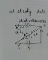
The circuit consists of two resistances of values 2R and 3R, two identical capacitors of capacitance C,
two identical inductors each of inductance L and an ideal battery of emf 'ε ' and a switch ‘S’. Initially
the switch is closed and the circuit is in steady state. V is an ideal volt meter with its terminals as
indicated in the diagram (diagram is attached below...)
Relevant Equations
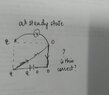
I've learnt that at steady state the capacitor is fully charged and so no current flows through that branch, and at steady state an inductor behaves like it's short circuited I.e. it just lets all the current flow through it. I guess the question is based on this concept only, not really sute if there are any specific formulas involved... I also know KVL(Kirchoff s voltage law) but I'm not sure how to use that here
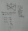
I did try redrawing the circuit at steady state , but I'm not really sure. I have attached the circuit that I tried drawing, I assumed the branch with the capacitors to be absent at steady state since current won't flow through them anyway. With this diagram I get the correct answer for Q 19 , but want to know if the method is correct or not.
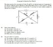
And please help with Q.20 I honestly don't know how to proceed.

(Attaching the question below too...)

Answers given 19 -AC , 20- AC
 

Attachments

  • 20210617000733.jpg
    20210617000733.jpg
    46.1 KB · Views: 90
  • IMG_20210617_012101.jpg
    IMG_20210617_012101.jpg
    23.5 KB · Views: 98
Last edited:
  • Like
Likes Delta2
Physics news on Phys.org
  • #2
user1296 said:
I get the correct answer for Q 19 , but want to know if the method is correct or not.
No, you got it by making two mistakes.
In the diagram you drew, one side of the voltmeter is not connected to anything, so it has no way to detect a potential difference. You should have got zero.
But I think you misinterpreted the original circuit diagram. In the centre, where the two lines cross in an X, you have taken the two wires as not being connected to each other. If that were the intention, it should show one wire as executing a small semicircle as it crosses the other. I believe you are supposed to take them as connected there.
 
  • Like
Likes Delta2
  • #3
I agree with @haruspex for Q19. Your equivalent schematic is not entirely correct. You should have drawn both the resistors of 3R and 2R in that schematic. Try again. Hint: One end of the voltmeter is connected to one end of the resistor 3R and the other end of the voltmeter is connected to one end of the resistor 2R.

Now for Q20 let's start from the easy ones:
can you argue why 20 C is correct? What will be the current in the 3R and 2R resistors long time after the switch is opened? Hence what will be their potential differences according to Ohm's law? How their potential differences are related to the reading of the voltmeter?
 
  • #4
haruspex said:
No, you got it by making two mistakes.
In the diagram you drew, one side of the voltmeter is not connected to anything, so it has no way to detect a potential difference. You should have got zero.
But I think you misinterpreted the original circuit diagram. In the centre, where the two lines cross in an X, you have taken the two wires as not being connected to each other. If that were the intention, it should show one wire as executing a small semicircle as it crosses the other. I believe you are supposed to take them as connected there.
Oh yes yes thank you. I redrew the circuit... Now is it correct? Since the voltmeter is ideal ,current flowing through it will be 0( so in my diagram i1 = 0) , so can I say that the voltmeter is connected across the 2R resistor only and so will measure 'E ' as the potential difference?
 

Attachments

  • IMG_20210617_165344.jpg
    IMG_20210617_165344.jpg
    19.5 KB · Views: 76
  • Like
Likes Delta2
  • #5
I think you got it right now, both the equivalent schematic and the explanation.
 
  • Like
Likes user1296
  • #6
Delta2 said:
I agree with @haruspex for Q19. Your equivalent schematic is not entirely correct. You should have drawn both the resistors of 3R and 2R in that schematic. Try again. Hint: One end of the voltmeter is connected to one end of the resistor 3R and the other end of the voltmeter is connected to one end of the resistor 2R.

Now for Q20 let's start from the easy ones:
can you argue why 20 C is correct? What will be the current in the 3R and 2R resistors long time after the switch is opened? Hence what will be their potential differences according to Ohm's law? How their potential differences are related to the reading of the voltmeter?
Yes thank you , I understood your hint& tried redrawing the circuit and attached it in the above post... Hope I've got it right this time...For Q 20,
After a long time I'm not really sure but I guess current will be 0?
So then the voltmeter will also measure 0...
 
  • Like
Likes Delta2
  • #7
user1296 said:
For Q 20,
After a long time I'm not really sure but I guess current will be 0?
So then the voltmeter will also measure 0...
Yes I think that's correct. But do you know why the currents will be zero after long time (theoretically infinite time , but practically it depends on the values of L,C,R)
 
  • #8
Delta2 said:
Yes I think that's correct. But do you know why the currents will be zero after long time (theoretically infinite time , but practically it depends on the values of L,C,R)
I'm not really sure why... I just thought maybe after infinite time the inductors and resistors will lose all energy through heat and so then there will be no current left... Just guessed not sure
 
  • Like
Likes Delta2
  • #9
user1296 said:
I'm not really sure why... I just thought maybe after infinite time the inductors and resistors will lose all energy through heat and so then there will be no current left... Just guessed not sure
That is almost correct , to state it a bit more carefully, the energy stored in the inductors and capacitors will be converted to heat over the resistors (2R and 3R) until there is no electromagnetic energy in the circuit, hence no currents.
Have you been taught the equations of an RLC circuit?. That if we start with some energy stored in the capacitor and/or the inductor, (and no EMF source present) then the current in the circuit does exponentially decaying oscillations?
 
  • #10
Delta2 said:
That is almost correct , to state it a bit more carefully, the energy stored in the inductors and capacitors will be converted to heat over the resistors (2R and 3R) until there is no electromagnetic energy in the circuit, hence no currents.
Have you been taught the equations of an RLC circuit?. That if we start with some energy stored in the capacitor and/or the inductor, (and no EMF source present) then the current in the circuit does exponentially decaying oscillations?
Yes yes, I've learned about LC oscillations
 
  • #11
user1296 said:
Yes yes, I've learned about LC oscillations
Very well, here in order to be more accurate we will have damped LC oscillations because there are resistors connected as well.
 
  • Like
Likes user1296
  • #12
Delta2 said:
Very well, here in order to be more accurate we will have damped LC oscillations because there are resistors connected as well.
Ohh okayy I think I understood Q20 C option...Thank you
But what about option A ? I just know what currents through the inductors won't change suddenly when the switch is opened, but I don't know how to proceed & find the potential difference... Please help
 
  • #13
user1296 said:
Ohh okayy I think I understood Q20 C option...Thank you
But what about option A ? I just know what currents through the inductors won't change suddenly when the switch is opened, but I don't know how to proceed & find the potential difference... Please help
Can you redraw the equivalent circuit when the switch is opened (effectively remove the EMF source).
 
  • #14
As you said the current through the inductors will not change suddenly, in order to be more accurate, it will still be the same right after the switch is opened. But the current from each inductor will follow a different route. You have to redraw the circuit first to proceed to further discussion.
 
  • #15
Yes I redrew it and I think I got the answer...is this the correct method ?
 

Attachments

  • IMG_20210617_181824.jpg
    IMG_20210617_181824.jpg
    28.9 KB · Views: 71
  • Like
Likes Delta2
  • #16
Yes I think your method is absolutely correct.
 
  • Like
Likes user1296
  • #17
Thank you for your help! :)

I just had a small doubt in the last circuit that I drew in the earlier post(#15) , If V is at a greater potential than V1 (since initially also current was flowing that way) then why does the current flow back from point V1 to V again from the right side of the loop ?
 
  • #18
user1296 said:
Thank you for your help! :)

I just had a small doubt in the last circuit that I drew in the earlier post(#15) , If V is at a greater potential than V1 (since initially also current was flowing that way) then why does the current flow back from point V1 to V again from the right side of the loop ?
because it flows through inductor and capacitor from the right side of the loop. if we remove the inductor and capacitor and replace them with resistors, this circulation of current wouldn't be possible indeed. For resistors the current always flows from higher to lower potential but this is not always the case for inductors and capacitors.
 
  • Like
Likes user1296
  • #19
Delta2 said:
because it flows through inductor and capacitor from the right side of the loop. if we remove the inductor and capacitor and replace them with resistors, this circulation of current wouldn't be possible indeed. For resistors the current always flows from higher to lower potential but this is not always the case for inductors and capacitors.
Ohh okay ..Thank you👍
 
  • #20
More specifically, when capacitor is charging, current flows from the positive plate to the negative plate, hence from high to low potential. However when capacitor is discharging , the current flows from the negative plate to the positive plate that is from low potential to high potential. Similar results hold for the inductor.

When you do AC circuits, you will learn this in a bit different way: We say there that the voltage in the capacitor lags phase ##\pi/2## with respect to the current that flows within it and that the voltage of inductor is ahead phase ##\pi/2## with respect to the current that flows within it. The voltage of the resistor is always in phase with respect to its current .
 
  • Like
Likes user1296
  • #21
Delta2 said:
More specifically, when capacitor is charging, current flows from the positive plate to the negative plate, hence from high to low potential. However when capacitor is discharging , the current flows from the negative plate to the positive plate that is from low potential to high potential. Similar results hold for the inductor.
Ooh ok ok , didn't think of this that way
Thank you!
 
  • Like
Likes Delta2

1. What is the difference between a resistor, capacitor, and inductor in an electrical circuit?

A resistor is an electrical component that limits the flow of current in a circuit. A capacitor stores electrical energy in the form of an electric field. An inductor stores electrical energy in the form of a magnetic field.

2. How do I calculate the total resistance in a series or parallel circuit?

In a series circuit, the total resistance is equal to the sum of all individual resistances. In a parallel circuit, the total resistance can be calculated using the formula 1/Rt = 1/R1 + 1/R2 + 1/R3 + ..., where Rt is the total resistance and R1, R2, R3, etc. are the individual resistances.

3. What is the purpose of a capacitor in an electrical circuit?

A capacitor is used to store and release electrical energy in a circuit. It can also be used to block direct current while allowing alternating current to pass through.

4. How does an inductor affect the flow of current in a circuit?

An inductor resists changes in the flow of current, so it can cause a delay or phase shift in the current. It also stores energy in its magnetic field and releases it when the current changes.

5. What is the relationship between voltage, current, and resistance in an electrical circuit?

According to Ohm's Law, voltage is equal to the current multiplied by the resistance (V = IR). This means that as resistance increases, the voltage also increases, and as resistance decreases, the voltage decreases.

Similar threads

  • Introductory Physics Homework Help
Replies
9
Views
322
  • Introductory Physics Homework Help
Replies
5
Views
229
  • Introductory Physics Homework Help
Replies
15
Views
987
  • Introductory Physics Homework Help
Replies
20
Views
414
  • Introductory Physics Homework Help
Replies
4
Views
786
  • Introductory Physics Homework Help
Replies
3
Views
730
  • Introductory Physics Homework Help
Replies
6
Views
296
  • Introductory Physics Homework Help
Replies
6
Views
1K
  • Introductory Physics Homework Help
Replies
9
Views
1K
  • Introductory Physics Homework Help
Replies
9
Views
610
Back
Top