A Question about Voltage Sources in Parallel

Join the discussion
Ask a follow-up here, or get your own question answered by working scientists, mathematicians and engineers — people, not an autocomplete.
Real named experts · corrections over time · the nuance an AI answer skips
5 replies · 4K views
bibo_dvd
Messages
37
Reaction score
0
Hello Guys !

My Question : in this photo i found That Total Resistance will be = 7 ohm .

and I2 = 12 / 7= 1.71 A and I1 = 0.5 * I2= 0.5 * 1.71= 0.85 A

I can't understand why I1= 0.5 I2 ?? and why it isn't the same of I2 ??

here is the photo
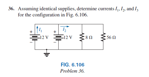
EbAEdiB.png


Thank you Guys ! :))
 
Physics news on Phys.org
The circuit is very unrealistic since voltage sources are not normally put in parallel for two reasons:

(1) If they are ideal voltages sources with the same voltage then one of them is redundant and if they are NOT the same voltage then they create a contradiction by definition
(2) If they are not ideal voltage sources then one of them will have a slightly higher voltage and may damage the other one

That said, the circuit as drawn, assuming ideal voltage sources, should have I1=I2
 
phinds said:
The circuit is very unrealistic since voltage sources are not normally put in parallel for two reasons:

(1) If they are ideal voltages sources with the same voltage then one of them is redundant and if they are NOT the same voltage then they create a contradiction by definition
(2) If they are not ideal voltage sources then one of them will have a slightly higher voltage and may damage the other one

That said, the circuit as drawn, assuming ideal voltage sources, should have I1=I2

This is not correct.

I1 is the current from 1 battery, I2 is the current from both batteries so will be double I1.

Note that this is a very common configuration is small battery driven devices.
 
No. I2 is the combined current of I1 and the current which is not labeled from the rightmost 12 volt battery. The drawing is crowded together so it makes it looks like I2 is the current in the rightmost battery.
-
Now as far as voltage sources not normally put in parallel. That is a stretch. Many 12 volt automotive batteries are in parallel in diesels due to the higher starter current required. Semi tractors can have more than 2 in parallel. Don't get me wrong, there can be issues associated with voltage sources in parallel but it doesn't apply in this thread since the problem said to assume ideal supplies.

Edit: Integral beat me to it.
 
I1 is definitely half of I2, if both are matched voltage source. There is no doubt about it.

What I am thinking is that this schematic can't be analyzed using superposition theorem. So it might not be realistic. For starter circuits, do all voltage sources (in parallel) operate in normal mode or are switched out ?