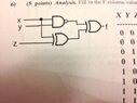
Analysis. Fill in the F column values in the truth table for the circuit.

In summary, the conversation was about filling in the F column values in a truth table for a circuit. The circuit involved the use of the Sheffer stroke (NAND) logic gate, which was defined as $f=(x \uparrow y) \oplus (x \oplus z)$. The conversation also included a discussion about applying DeMorgan's law correctly to calculate NAND operations.
  • #1
shamieh
539
0
Fill in the F column values in the truth table for the circuit.
Need someone to check my work.

View attachment 1444

My Answer:
  • x y z | f | x! and y! | x! XOR z|
  • 0 0 0| 0 | 1 | 1
  • 0 0 1| 1 | 1 | 0
  • 0 1 0| 1 | 0 | 1
  • 0 1 1| 0 | 0 | 0
  • 1 0 0| 0 | 0 | 0
  • 1 0 1| 1 | 0 | 1
  • 1 1 0| 1 | 1 | 0
  • 1 1 1| 0 | 1 | 1
 

Attachments

  • photo.JPG
    photo.JPG
    25.8 KB · Views: 44
Technology news on Phys.org
  • #2
So, let's define the $\uparrow$ symbol as the Sheffer stroke, which corresponds to the NAND logic gate you have there. Then $f=(x \uparrow y) \oplus (x \oplus z)$. The truth table is then
$$
\begin{array}{c|c|c|c|c|c}
x &y &z &x \uparrow y &x \oplus z &(x \uparrow y) \oplus (x \oplus z) \\ \hline
0 &0 &0 &1 &0 &1 \\
0 &0 &1 &1 &1 &0 \\
0 &1 &0 &1 &0 &1 \\
0 &1 &1 &1 &1 &0 \\
1 &0 &0 &1 &1 &0 \\
1 &0 &1 &1 &0 &1 \\
1 &1 &0 &0 &1 &1 \\
1 &1 &1 &0 &0 &0
\end{array}
$$
 
  • #3
Okay, I see where I went wrong. But you're saying x NAND y in the first row is 0 NAND 0 which is really 1 AND 1 = 1. I get that. Then you are saying in the 2nd row the same thing 0 NAND 0 = 1 because it's really 1 AND 1. Then in the 3rd row you are saying 0 NAND 1 which is really 1 AND 0 = 1. But how does that = 1? 1 AND 0 = 0. It only equals 1 if both are 1.
 
  • #4
shamieh said:
Okay, I see where I went wrong. But you're saying x NAND y in the first row is 0 NAND 0 which is really 1 AND 1 = 1.

Actually not. The NAND operation means "not both". If I say $x \uparrow y$, or $x$ NAND $y$, that is equivalent to $\overline{xy}$. By DeMorgan, $ \overline{xy}= \bar{x}+ \bar{y}$, not $ \underbrace{\overline{xy}= \bar{x} \bar{y}}_{\text{Wrong!}}$.

I get that. Then you are saying in the 2nd row the same thing 0 NAND 0 = 1 because it's really 1 AND 1. Then in the 3rd row you are saying 0 NAND 1 which is really 1 AND 0 = 1. But how does that = 1? 1 AND 0 = 0. It only equals 1 if both are 1.

Again, this reasoning is flawed. If you need to, calculate NAND's like this: to compute $x \uparrow y$, first compute $xy$, and then negate the result. You cannot compute NAND's by negating the $x$ and $y$ first, and then AND'ing the results.
 
  • #5
Ahh! I see! So DeMorgans law changes the ANDing of xy to OR, while negating the terms as well. x! + y! ok. Going to re-work it and make sure I get the correct solution. I'll be back (Wait)

- - - Updated - - -

Awsome, thank you for the detailed explanations. (Sun)
 

Related to Analysis. Fill in the F column values in the truth table for the circuit.

1. What is analysis?

Analysis is the process of breaking down a complex system or problem into smaller, more manageable parts in order to better understand it.

2. Why is analysis important in science?

Analysis allows scientists to study and understand the underlying mechanisms and relationships within a system, leading to a deeper understanding of how it works and how it can be improved.

3. What is a truth table in analysis?

A truth table is a visual representation of the possible combinations of inputs and outputs in a logical circuit or system. It helps to determine the truth value of a statement or combination of statements.

4. How do you fill in the F column values in a truth table?

To fill in the F column, you must first identify the inputs and outputs of the circuit or system. Then, using the logical operators (AND, OR, NOT), you can determine the output value for each combination of inputs. This value is then entered into the F column.

5. What information can be obtained from a truth table?

A truth table can provide information about the logical relationships between inputs and outputs in a system. It can also help to identify any errors or discrepancies in the circuit design.

Similar threads

  • Programming and Computer Science
Replies
1
Views
1K
  • Programming and Computer Science
Replies
4
Views
649
  • Programming and Computer Science
Replies
1
Views
774
Replies
1
Views
1K
  • Programming and Computer Science
Replies
9
Views
1K
  • Programming and Computer Science
Replies
1
Views
1K
  • Programming and Computer Science
Replies
15
Views
1K
  • Programming and Computer Science
Replies
1
Views
659
  • Programming and Computer Science
Replies
3
Views
396
  • Programming and Computer Science
Replies
2
Views
883
Back
Top