Current Divider Circuit (Find a Resistance)

In summary: The numerator in the current divider equation should be the sum of the two individual current expressions, not just the total current. In summary, the textbook says that the resistor R should be 30 ohms, but the current divider equation says that it should be 720 ohms. I'm completely lost.
  • #1
johnsmith7565
13
4
Homework Statement
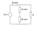
Find The Value Of R That Will Carry a 4 A Of Current To Flow Through The 80 Ohm Resistor In The Circuit Shown.
Relevant Equations
Parallel Circuit rules and Series circuit rules, i0 = (R1)/(R1+R2)is, where “is” is the source current, R1 and R2 are the resistances, and i0 is the current across a resistor.
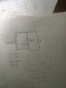
The resistors are all in series , with exception of R, so I added them together and then used the current divider equation to solve for R, and I got 720 ohms. The textbook says R should be 30 ohms. I’m completely lost.
 

Attachments

  • 285DD4B0-B51F-4C16-96F9-F54B057404D6.png
    285DD4B0-B51F-4C16-96F9-F54B057404D6.png
    2 KB · Views: 97
  • 4E7696D5-01D9-451C-B138-C2E864DA1768.jpeg
    4E7696D5-01D9-451C-B138-C2E864DA1768.jpeg
    20.4 KB · Views: 83
Physics news on Phys.org
  • #2
Hi @johnsmith7565 ,

Welcome to Physics Forums.

Note that the ##60 Ω## resistor is not in series with the ##40 Ω## and ##80 Ω## resistors; The existence of the resistor ##R## precludes that.

What you can say is that 20 A enters the top node from the direction of the source, and that it must divide between the two parallel branches. Write your current division expression so that it divides the 20 A as required using only the three resistors of the parallel branches.
 
  • Like
Likes johnsmith7565
  • #3
gneill said:
Hi @johnsmith7565 ,

Welcome to Physics Forums.

Note that the ##60 \Ohm## resistor is not in series with the ##40 \Ohm## and ##80 \Ohm## resistors; The existence of the resistor ##R## precludes that.

What you can say is that 20 A enters the top node from the direction of the source, and that it must divide between the two parallel branches. Write your current division expression so that it divides the 20 A as required using only the three resistors of the parallel branches.
I still don’t understand. So the 40 ohm resistor and the 80 ohm one are in series so I add them, and now my equation is 4=(20)(120/R+120) and R is still too large.
 
  • #4
johnsmith7565 said:
I still don’t understand. So the 40 ohm resistor and the 80 ohm one are in series so I add them, and now my equation is 4=(20)(120/R+120) and R is still too large.
I think you'll want to take a closer look at the current divider expression. Let's say you have two parallel resistances A and B with some total current ##I## being split between them. Then you can write:

##I_A = I \cdot \frac{B}{A + B}##

##I_B = I \cdot \frac{A}{A + B}##

Make sure that you get your numerator correct!
 
  • Like
Likes Greg Bernhardt, DaveE and johnsmith7565

1. How does a current divider circuit work?

A current divider circuit is a type of circuit that splits the current flowing through it into multiple branches. This is achieved by using resistors in parallel, which creates multiple paths for the current to flow through. The amount of current flowing through each branch is determined by the resistance of the resistor in that branch.

2. How do I calculate the resistance in a current divider circuit?

The total resistance in a current divider circuit is equal to the sum of the resistances in each branch. To find the resistance in a specific branch, you can use the formula R = (R1 * R2) / (R1 + R2), where R1 and R2 are the resistances in the two branches.

3. Can I use different types of resistors in a current divider circuit?

Yes, you can use different types of resistors in a current divider circuit as long as they have the same value. This is because resistors in parallel have the same voltage across them, so they must have the same resistance to ensure that the current is divided evenly.

4. How does the voltage affect the current in a current divider circuit?

In a current divider circuit, the voltage across each branch is equal to the total voltage of the circuit. This means that the voltage does not affect the current in each branch, but rather the resistance of the resistor in that branch determines the amount of current flowing through it.

5. What is the purpose of a current divider circuit in a circuit?

A current divider circuit is often used in circuits to control the amount of current flowing through different branches. This can be useful in situations where certain components require a specific amount of current to function properly. It can also be used to reduce the overall resistance in a circuit, which can help prevent overheating and damage to the circuit.

Similar threads

  • Engineering and Comp Sci Homework Help
Replies
5
Views
3K
  • Engineering and Comp Sci Homework Help
Replies
1
Views
1K
  • Engineering and Comp Sci Homework Help
Replies
20
Views
1K
  • Engineering and Comp Sci Homework Help
Replies
3
Views
807
  • Engineering and Comp Sci Homework Help
Replies
4
Views
1K
  • Engineering and Comp Sci Homework Help
Replies
7
Views
886
  • Introductory Physics Homework Help
2
Replies
42
Views
1K
  • Engineering and Comp Sci Homework Help
Replies
10
Views
2K
  • Engineering and Comp Sci Homework Help
Replies
8
Views
1K
  • Engineering and Comp Sci Homework Help
Replies
18
Views
2K
Back
Top