zxcvb
- 10
- 1
- TL;DR
- I am preparing to use an ultrasonic transmitter and receiver to make an ultrasonic sensor circuit, and then connect it with the single-chip microcomputer msp430 to realize the functions of speed measurement and numerical display.
Hello everyone, I am studying abroad and I am working on a speedometer project.
I am preparing to use an ultrasonic transmitter and receiver to make an ultrasonic sensor circuit, and then connect it with the single-chip microcomputer msp430 to realize the functions of speed measurement and numerical display.
I am temporarily in charge of the hardware module.
I don't know much about circuit diagrams, and I have many questions to ask.
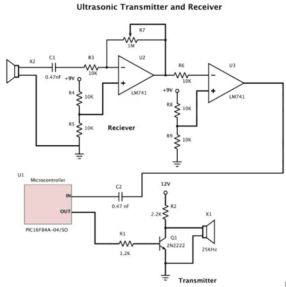
I am preparing to use an ultrasonic transmitter and receiver to make an ultrasonic sensor circuit, and then connect it with the single-chip microcomputer msp430 to realize the functions of speed measurement and numerical display.
I am temporarily in charge of the hardware module.
I don't know much about circuit diagrams, and I have many questions to ask.
- I chose a 40Khz ultrasonic transmitter and receiver. Does the circuit I need to generate a frequency of 40Khz? Can this step be achieved by MSP430?
- What circuit do I need to make between the transmitter and receiver? What function?
- I found this circuit design on the Internet, but it is for a 25Khz sensor. Can I use it?
- What are the values of resistors and capacitors based on?