Drawing a Wheel Under Acceleration - RWD Car

Join the discussion
Ask a follow-up here, or get your own question answered by working scientists, mathematicians and engineers — people, not an autocomplete.
Real named experts · corrections over time · the nuance an AI answer skips
7 replies · 9K views
PhysicsN_b
Messages
6
Reaction score
0
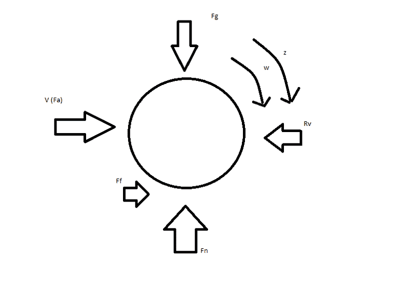
I drew up a quick picture in paint of a wheel under acceleration. This is the driving wheel of a RWD car. Am I missing any forces/drawn in the wrong direction?
FBDWheel.png


Thanks.
 
Physics news on Phys.org
Assuming all the forces are supposed to be external forces applied to the wheel, then friction force from the road to the tire would be to the right, and the reaction force of the car to acceleration, F = m a, would be to the left and same magnitude as friction force. You also have a clockwise torque force on the wheel from the rear axle (negative sign if using conventional angular math), almost all opposed by the counter clockwise torque related road force and car reaction force. The net torque on the wheel would correspond to the rate of angular acceleration of the wheel divided by it's angular inertia. If you assume that angular inertia of the wheel is zero, then net torque is zero.
 
Last edited:
Updated.

FBDWheel-2.png


Assume Rv to be the reaction force of the car on the wheel, and I labeled the angular acceleration z since I cannot due Greek letters in paint. This is correct now right?
 
There is no force V(Fa) acting on the wheel. Fg and Fn should have equal magnitude. Ff and Rv should have equal magnitude. Apparently you're not concerned about torques on the wheel.
 
I don't understand how I am not concerned with the torque applied on the wheel. If there is angular acceleration on the wheel, there has to be a torque applied. Also, the wheel has to be applying a forward force V(Fa) for the car to accelerate in speed correct, so at the axle there would be a forward force applied? I don't understand what I am missing.
 
PhysicsN_b said:
I don't understand how I am not concerned with the torque applied on the wheel. If there is angular acceleration on the wheel, there has to be a torque applied.
If your model uses a non-zero value for angular inertia of the wheel then there's a small net torque on the wheel, most of the torque ends up accelerating the car. If your model uses a zero value for angular inertia of the wheel, then there is no torque due to angular acceleration of a massless wheel, and all of the torque ends up accelerating the car.

PhysicsN_b said:
Also, the wheel has to be applying a forward force V(Fa) for the car to accelerate in speed correct, so at the axle there would be a forward force applied?
A free body diagram is supposed to show only the forces acting on the wheel, and not the forces generated by the wheel.
 
Okay. So the only thing I need to get rid of is V(Fa) and 'say' that z is non zero and it should be perfect to be an example of a driving/accelerating wheel?
 
PhysicsN_b said:
Okay. So the only thing I need to get rid of is V(Fa) and 'say' that z is non zero and it should be perfect to be an example of a driving/accelerating wheel?
Close enough. In the real world, there would be rolling resistance, aerodynamic drag, energy losses in the drive train, but for a typical physics problem, it's good enough.