I Effects of altitude on liquid CO2 utilization

  • I
  • Thread starter Thread starter MrFreezeMiser
  • Start date Start date
  • Tags Tags
    Altitude
AI Thread Summary
Using liquid CO2 (LCO2) for freezing water pipes shows significant differences in efficiency between high and low altitudes, with much more LCO2 required in Denver (5,300 feet) compared to Detroit (1,000 feet). The contractor has observed that freezing times and LCO2 consumption are notably longer in Denver, although no specific data has been collected yet. The discussion highlights the impact of atmospheric pressure on LCO2's phase and performance, suggesting that lower pressure may lead to faster sublimation of CO2, affecting freezing efficiency. There is a lack of manufacturer guidance on altitude adjustments for freeze times, leaving the contractor seeking theoretical explanations for these discrepancies. Understanding the relationship between altitude, pressure, and CO2 behavior is crucial for optimizing LCO2 usage in pipe freezing applications.
MrFreezeMiser
Messages
26
Reaction score
13
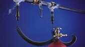
I’m a contractor using liquid CO2 (LCO2) to freeze water pipes (for valve maintenance) while the water service remains at full static pressure (i.e., water is not flowing).

I do the work in two locations: (1) near Denver, CO, where the altitude is 5,300 feet and (2) near Detroit, MI where the altitude is 1,000ft. Interestingly, I’ve found it takes WAY MORE LCO2 to do the same work in Denver than Detroit. At this point, I don’t have any data collected (i.e., water temp, ambient temp, etc.), so initially I’m looking at things theoretically with anecdotal observations.

My question here is: Assuming exact same situations (i.e., same copper pipe material, same size, same potable water temperature, etc.), how could one calculate and/or quantify the effects of altitude on LCO2 utilization? In other words, given the exact same work but at two materially-different altitudes, how many fewer pipes would be expected to be frozen with the same volume of LCO2 (e.g., standard 20-lb cylinder) in Denver vs. Detroit?

The last freeze in Detroit was a 1-inch type-M copper pipe, and it took 10-minutes (note: consistent with manufacturer’s specifications ) and used approximately 3-lbs of LCO2. The manufacturer of the freeze equipment does not provide adjustments for freeze times with higher altitudes, but I can state in Denver it seems to take a lot more time and use more LCO2.

Thank you in advance. -Mr. Freeze Miser
 
Last edited by a moderator:
Science news on Phys.org
Air pressure in Denver is about 85% what it is in Detroit. What is the pressure of the liquid CO2? Is it pressurized or atmospheric pressure(Can CO2 even be liquid at atmospheric pressure?)? Do you have a table of boiling point vs pressure? If the system is a pressurized cylinder eventually discharging to atmosphere can you put a valve at the end to throttle it and increase the pressure?
 
My guess is that if what you say is true, then it must be that the CO2 evaporates (sublimates?) more rapidly with lower ambient pressure. But I don't know how your machine works and how that matches up with the CO2 phase diagram. If it's truly liquid for any significant length of time then it's pressure must be much greater than 1 atm.

1705173541830.png
 
MrFreezeMiser said:
full static pressure
Denver vs. Detroit? How much difference? You're looking at two different public utilities.
 
Copied from
https://www.plumbermag.com/how-to-a...out_shutting_down_the_whole_building_sc_01ck7

"The system freezes all types of liquids in steel, copper, cast iron, aluminum and plastic pipes ranging from 1/8 to 2 inches. The freeze kit uses carbon dioxide (CO2) from a dip-tube tank available at all welding supply houses. The cold liquid CO2 is minus 110 degrees so it can freeze the water in just minutes. A 1/2-inch copper pipe freezes in just five minutes, or just three minutes in cast iron. The ice plug is so strong it can withstand up to 7,000 psi."


Attachments

  • int&fit=crop&fp-x=0.5&fp-y=0.5&h=563&ixlib=php-1.1.jpg
    int&fit=crop&fp-x=0.5&fp-y=0.5&h=563&ixlib=php-1.1.jpg
    28.3 KB · Views: 85
Last edited:
MrFreezeMiser said:
The last freeze in Detroit was a 1-inch type-M copper pipe, and it took 10-minutes (note: consistent with manufacturer’s specifications ) and used approximately 3-lbs of LCO2. The manufacturer of the freeze equipment does not provide adjustments for freeze times with higher altitudes, but I can state in Denver it seems to take a lot more time and use more LCO2.
Please, see:
https://www.engineeringtoolbox.com/CO2-carbon-dioxide-properties-d_2017.html

https://homesteady.com/how-6514409-calculate-flow-based-differential-pressure.html

"The change in freezing point (water inside pipe if system is opened to atmosphere) at different altitudes is much smaller than the change in the boiling point (liquid CO2 expanding to atmospheric pressure).
The freezing point increases very slightly at higher altitudes, due to the air pressure. Because ice takes up more space than water, a lower air pressure will cause water to freeze at a slightly higher temperature."

CO2%20phase%20diagram.jpg
 
russ_watters said:
(Can CO2 even be liquid at atmospheric pressure?)
Yes, but not for long. Please don't ask me how I know this...

Broken LCO2 connection from a dewar that I had to deal with in the lab -- crazy.

1705194945479.jpeg

https://newbestsm.live/product_details/47728720.html
 
russ_watters said:
Air pressure in Denver is about 85% what it is in Detroit. What is the pressure of the liquid CO2? Is it pressurized or atmospheric pressure(Can CO2 even be liquid at atmospheric pressure?)? Do you have a table of boiling point vs pressure? If the system is a pressurized cylinder eventually discharging to atmosphere can you put a valve at the end to throttle it and increase the pressure?
Thank you, Russ! I’m not certain exactly what the pressure is. It’s not high but not low either. Open the valve to atmosphere and it’s going to be loud and sporty. The LCO2 tank has a dip tube so the LCO2 is forced out vs. gas. As the tank empties you still get CO2 but it’s no longer liquid. The device sprays LCO2 literally (but lightly) on the pipe. Eventually it freeze a plug inside the pipe and about a 3/4” thick x 3/4” wide ice ring on the outside. You keep it running the entire time you’re doing work, then shut it off and about 5-mins after, flow naturally restores itself. One other note is the tubing coming from the tank connection is like 1/8” OD. You’d think that would freeze solid and snap with LC02 going through it! But it stays springy/coiled (stretchable to about 10ft). At the tank, you connect the manufacturer’s adapter and flow of LCO2 is ”regulated” by a sintered brass filter device. There is no regulator; only flow control is the tank’s valve (on/off). Lnewqban (thanks!) posted a link to the ColdShot which is what I’m using.
 
DaveE said:
My guess is that if what you say is true, then it must be that the CO2 evaporates (sublimates?) more rapidly with lower ambient pressure. But I don't know how your machine works and how that matches up with the CO2 phase diagram. If it's truly liquid for any significant length of time then it's pressure must be much greater than 1 atm.

View attachment 338510
Thanks, Dave. I think you’re on to something here. Sublimation with LCO2 is totally new to me, so I will get familiar with it. I bought this setup based upon manufacturer’s representations. It says freezing results will vary…but I didn’t expect such dramatic difference. Unfortunately, there’s no mention specifically of altitude effects. Needless to say, in Denver I BLOW THROUGH LCO2 vs. doing exact same work in Detroit. I’m really fascinated by all this vs. have any hard feelings with the manufacturer. I will say high school and undergrad physics never prepared me for this!🤨 Hopefully the brains of this forum can help explain what’s really going on and perhaps share this most interesting, real-world work scenario with world.
 
  • #10
Lnewqban said:
Copied from
https://www.plumbermag.com/how-to-a...out_shutting_down_the_whole_building_sc_01ck7

"The system freezes all types of liquids in steel, copper, cast iron, aluminum and plastic pipes ranging from 1/8 to 2 inches. The freeze kit uses carbon dioxide (CO2) from a dip-tube tank available at all welding supply houses. The cold liquid CO2 is minus 110 degrees so it can freeze the water in just minutes. A 1/2-inch copper pipe freezes in just five minutes, or just three minutes in cast iron. The ice plug is so strong it can withstand up to 7,000 psi."


Thanks, Lnewqban. Yes, this is the system I’m using. I cross-sectioned an ice plug with 3/4” CPVC and was super impressed by the very dense ice…extremely robust.
 
  • #11
Bystander said:
Denver vs. Detroit? How much difference? You're looking at two different public utilities.
Bystander said:
Denver vs. Detroit? How much difference? You're looking at two different public utilities.
According to Russ, it appears pressure is approx 15% less in Denver. I do private, commercial work vs. work for public utilities.
 
  • #12
On an interesting side note, when I asked my Denver LCO2 gas supplier why utilization here was falling off the charts, the sales manager said he couldn’t explain why but said altitude has a huge effect. Then he shared this example, and brace yourself this get weird. It supplied the liquid nitrogen to keep some frozen guy frozen (yes, it’s a creepy tourist attraction!) while in transport being relocated from Nederland, CO to Estes Park, CO. The planners said/ordered 6 large liquid N tanks. Needless to say there was serious panic because they made emergency requests for more and more tanks of LN. I think he said they ended up using 20 tanks instead of 6. This is consistent with my LCO2 experience.
 
  • #13
berkeman said:
Yes, but not for long. Please don't ask me how I know this...

Broken LCO2 connection from a dewar that I had to deal with in the lab -- crazy.

View attachment 338528
https://newbestsm.live/product_details/47728720.html
lol…we don’t need to know! I’ve done plumbing work for companies the use a lot of LCO2 and CO2…never pleasant when things go sideways. Thankfully, I haven’t triggered any of the alarm systems yet!
 
  • #14
MrFreezeMiser said:
One other note is the tubing coming from the tank connection is like 1/8” OD. You’d think that would freeze solid and snap with LC02 going through it!
A misunderstanding.
Why should the tube 'freeze'?
The liquid CO2 in the bottle is at room temperature.
So is the liquid CO2 passing through the tube.
 
  • Like
Likes MrFreezeMiser
  • #15
I do hope you wear safety goggles for your eyes.
 
  • Like
Likes MrFreezeMiser
  • #16
Lnewqban said:
Copied from
https://www.plumbermag.com/how-to-a...out_shutting_down_the_whole_building_sc_01ck7

"The system freezes all types of liquids in steel, copper, cast iron, aluminum and plastic pipes ranging from 1/8 to 2 inches. The freeze kit uses carbon dioxide (CO2) from a dip-tube tank available at all welding supply houses. The cold liquid CO2 is minus 110 degrees so it can freeze the water in just minutes. A 1/2-inch copper pipe freezes in just five minutes, or just three minutes in cast iron. The ice plug is so strong it can withstand up to 7,000 psi."


According to the phase diagram for CO2 presented in post #6, at -110 C, CO2 is a solid. The temperature must be >-55 C and the pressure in the tank must be above 5 bars absolute (4 bars gauge, 60 psig) for there to be liquid CO2 in the tank.

Here is a pressure-enthalpy diagram for CO2.
1705233329543.png

At -40 C (=-40 F), the pressure in the tank is going to be about 140 psi (125 psig), and the CO2 exiting that valve and tubing will be a mixture of about 45% CO2 vapor and 55% CO2 solid (assuming constant enthalpy through the valve and tube), down to 15 psia. The temperature of this mixture will easily be <-40C, and could easily approach -110 C. The final pressure (1 bar vs 0.85 bar) could effect the final mixture temperature by about 10C (say -120 C vs -110 C, according to the diagram). This should not substantially affect the freezing time of the pipe.
 
Last edited:
  • Like
Likes 256bits, DaveE, MrFreezeMiser and 1 other person
  • #17
256bits said:
A misunderstanding.
Why should the tube 'freeze'?
The liquid CO2 in the bottle is at room temperature.
So is the liquid CO2 passing through the tube.
Yes, I agree it shouldn’t freeze. It’s just me and kind of like my response to a magic trick…it should, but it doesn’t.
 
  • #18
Chestermiller said:
... The final pressure (1 bar vs 0.85 bar) could effect the final mixture temperature by about 10C (say -120 C vs -110 C, according to the diagram). This should not substantially affect the freezing time of the pipe.
Could the difference in freezing time of the water plugs described in the OP be due to a reduced heat of sublimation of the gas at lower atmospheric pressure?
 
  • Like
Likes russ_watters
  • #19
MrFreezeMiser said:
According to Russ, it appears pressure is approx 15% less in Denver. I do private, commercial work vs. work for public utilities.
Water pressure; how hard a freeze to stop the flow? Two different public utilities, two different hydrant pressures.
 
  • Like
Likes russ_watters
  • #20
Chestermiller said:
This should not substantially affect the freezing time of the

I wouldn't think so either since the heat of vapourization of CO2 would be the dominant criteria for heat removal and stabilization.

Ideal case would be if the camber has a liquid-gaseous quality, with liquid mass flow input matching gaseous outflow,
Too too little liquid inflow and the quality within the chamber surrounding the water pipe would drop to 100% vapour. The benefit of the heat transfer due to heat of vapourization of CO2 would move from the chamber towards the direction of the tank along the piping.
Too too much liquid inflow and the quality would become saturated liquid. Liquid would exit the chamber and turn to the gaseous state outside the assembly, completely negating any cooling effect to the chamber.

I propose that the lower back pressure of the atmosphere inclines the liquid input into the chamber to increase, moving the quality of the CO2 towards a direction of more saturated liquid state. so that more CO2 liquid is escaping from the chamber and not contributing anything to the cooling effect of the chamber. It is throwing away liquid CO2. This can account for the increase in amount of CO2 usage.

The increased inflow of CO2 adds another burden for cooling according to the specific heat capacity of CO2 liquid, which has to be additionally cooled from the input temperature, say of the tank, to the freezing point of water and below.

The mass flow of the liquid CO2 is related to the pressure difference between the tank and the atmosphere, although not that large in quantity, does seem to be playing hacoc with the amount of CO2 usage at higher elevations.

Assumption of course is that there is not choked flow to limit and regulate CO2 liquid, gaseous or mixture through an exit orifice.
 
  • #21
Bystander said:
Water pressure; how hard a freeze to stop the flow? Two different public utilities, two different hydrant pressures.
Flow is stopped before when using this machine, ie some valve(s) are closed to prevent water flow into the section one is working on.
The ice plug(s) of ice are there so that whole of the pipe line does not have to be drained.
 
  • Like
Likes MrFreezeMiser
  • #22
Bystander said:
Water pressure; how hard a freeze to stop the flow? Two different public utilities, two different hydrant pressures.
It’s designed for static pressure only. There can be very little—preferably no flow.
 
  • #23
256bits said:
I wouldn't think so either since the heat of vapourization of CO2 would be the dominant criteria for heat removal and stabilization.

Ideal case would be if the camber has a liquid-gaseous quality, with liquid mass flow input matching gaseous outflow,
Too too little liquid inflow and the quality within the chamber surrounding the water pipe would drop to 100% vapour. The benefit of the heat transfer due to heat of vapourization of CO2 would move from the chamber towards the direction of the tank along the piping.
Too too much liquid inflow and the quality would become saturated liquid. Liquid would exit the chamber and turn to the gaseous state outside the assembly, completely negating any cooling effect to the chamber.

I propose that the lower back pressure of the atmosphere inclines the liquid input into the chamber to increase, moving the quality of the CO2 towards a direction of more saturated liquid state. so that more CO2 liquid is escaping from the chamber and not contributing anything to the cooling effect of the chamber. It is throwing away liquid CO2. This can account for the increase in amount of CO2 usage.

The increased inflow of CO2 adds another burden for cooling according to the specific heat capacity of CO2 liquid, which has to be additionally cooled from the input temperature, say of the tank, to the freezing point of water and below.

The mass flow of the liquid CO2 is related to the pressure difference between the tank and the atmosphere, although not that large in quantity, does seem to be playing hacoc with the amount of CO2 usage at higher elevations.

Assumption of course is that there is not choked flow to limit and regulate CO2 liquid, gaseous or mixture through an exit orifice.
Unscientifically…something like this is what I feel. The manual says a freeze of 1/2” copper pipe should take 5-mins AND you should get 30-freezes for 20-lb. cylinder. In Denver, it’s taking 5-mins, but I’m only getting 3 (maybe 4) freezes per cylinder. Now, I haven’t done 1/2” copper yet in Detroit, but I did do 1” copper, and it took 10-minutes and used 3-lbs using a refrigerant scale. So extrapolating this, I should get at least 6 freezes per cylinder. The manual suggests yield should be 15 freezes. Anyway, in Denver it just feels like LCO2 somehow just disappears.
 
Last edited:
  • #24
From the p-H diagram I presented in my previous post, if the temperature of the tank contents is ~70 F initially, it will be at 800 psig. What pressure does the regulator show initially? What is the volume of the tank. Is the amount of liquid CO2 initially in the tank really 20 lb?

I intend to do some serious calculations on this operation, including heat transfer and cooling/freezing of the water in the pipe.

At 1 bar,
saturation temperature -109 F
saturated solid density = 1.562 gm/cc
saturated vapor volume = 363 L/kg

At 20 C
Pressure = 5.729 bars = 830 psia
saturated liquid density =1.294 gm/cc
saturated vapor volume = 5.149 L/kg
 
Last edited:
  • Like
Likes MrFreezeMiser
  • #25
Based on equilibrium vapor pressure data, the temperature of the solid-vapor mixture coming out of the tubing should be about 8 F cooler for Denver than for Detroit (say, -117 F vs -109 F). The streams should have about the same mass fractions solid (pretty low). Based solely on these temperature of the streams, the water freezing at Denver should be more rapid than the water freezing at Detroit.

We know that the vapor flow rate affects the heat transfer. How do you know that the mass flow rates were approximately the same. given that, as the tank empties, the pressure in the tank decreases so that, at a given valve opening, there is decreasing flow as the tank empties.?
 
  • #26
Chestermiller said:
given that, as the tank empties, the pressure in the tank decreases so that, at a given valve opening, there is decreasing flow as the tank empties.?
The vapour volume within the tank increases as liquid is discharged, so there should be some boiling and temperature drop, unless the heat transfer from atmosphere to tank is able to keep up.
 
  • #27
256bits said:
The vapour volume within the tank increases as liquid is discharged, so there should be some boiling and temperature drop, unless the heat transfer from atmosphere to tank is able to keep up.
The temperature within the tank is indeed dropping, but there is only saturated vapor entering the exit tubing at the enthalpy of the saturated vapor. The enthalpy of this saturated vapor does not change in throttling though the valve and exit tubing, and, according to the diagram I presented in post #16, the temperature of the vapor leaving the tubing will be cooler in the tank due to Joule Thomson cooling. The highest the exit enthalpy from the tubing will be is 140 BTU/lb, and the highest the exit temperature will be is about -80 F for this maximum saturation enthalpy. Toward the end, when the pressure in the tank has dropped to about 1 bar, the exit temperature from the tubing will be about -109 F.
 
  • #28
I think that 256 nailed it in post #20.
The flow regulation in this setup is a function of differential pressure, where the low end is atmosphere. you're flowing more CO2 than you can effectively use (in Denver). I suspect (very strongly) that the addition of a 'throttle' ball valve (partially closed in Denver) will make 'Mile-High' performance very close to that of 'Motown'. There are some other differences, but flow regulation is the 'gorilla.'
 
  • Like
Likes MrFreezeMiser and russ_watters
  • #29
Chestermiller said:
From the p-H diagram I presented in my previous post, if the temperature of the tank contents is ~70 F initially, it will be at 800 psig. What pressure does the regulator show initially? What is the volume of the tank. Is the amount of liquid CO2 initially in the tank really 20 lb?

I intend to do some serious calculations on this operation, including heat transfer and cooling/freezing of the water in the pipe.

At 1 bar,
saturation temperature -109 F
saturated solid density = 1.562 gm/cc
saturated vapor volume = 363 L/kg

At 20 C
Pressure = 5.729 bars = 830 psia
saturated liquid density =1.294 gm/cc
saturated vapor volume = 5.149 L/kg
Unfortunately, the manufacturer doesn’t include a pressure gauge, but maybe I can get the data or see if the supplier can tell us. I have refrigeration pressure gauges that go to 800-psi, but now that you‘re suggesting it might be 800-psi or more, I might have to buy a higher limit gauge for testing. I have two tanks to refill in Denver, so I could get pressure at temperature from these close-to-empty tanks. Then when I get replacement tanks (supplier just swaps them), I could gather that data as well and post it.

Interestingly, today I tried to freeze 3/4” CPVC when the ambient temperature was approx 20ºF. I brought a full tank that was kept on the truck on it’s been like -5ºF here, so I bet the tank was somewhere around this temperature. As ironic as it sounds, yes, I was freezing pipes in freezing cold weather. And here I wanted to see what would happen in ambient conditions. My guess was just gas would come out based upon what I’ve learned from folks here. So after hooking up everything, yep, LCO2 would not flow. Only gas hissed like you hear when the LCO2 tank is close to empty. So I took one of our portable heaters and warmed up the tank really good [read: hot], and like magic, LCO2 began to flow like normal.

Typically, we freeze 3/4” CPVC for 20-minutes in Denver (no data for Detroit). Today, I did 25-mins—just to be certain—and it worked perfectly with pre-heated tank and maintaining heat throughout the process. But I bet I used a lot of that brand new 20-lb cylinder. These jobs are critical and consuming, so I forget to gather data to stay focused. I need to do better with this.

Supposedly cylinders are full with 20-lbs of LCO2 from the supplier. When I get replacements, I’ll get actual net weight(s). My guess is it’ll be 20-lbs or slightly over.
 
  • #30
Dullard said:
I think that 256 nailed it in post #20.
The flow regulation in this setup is a function of differential pressure, where the low end is atmosphere. you're flowing more CO2 than you can effectively use (in Denver). I suspect (very strongly) that the addition of a 'throttle' ball valve (partially closed in Denver) will make 'Mile-High' performance very close to that of 'Motown'. There are some other differences, but flow regulation is the 'gorilla.'
😭😭😭 I’m going to look into flow control. When I first starting doing this work, I was just happy it froze and my company didn’t cause an international incident! There’s no Blowout Preventer on this deal, so you have to be sure your work is as cool as the ice plug. Fascinating stuff! I so much appreciate everyone’s involvement and learning what’s really going on here. Plus, it will help me do smarter this work. “Mile High➡️Motown”…still🤣
 
  • #31
  • Like
Likes MrFreezeMiser
  • #32
Lnewqban said:
Caution with heating pressurized tanks is advised:
https://www.linde-gas.com/en/images/LMB_Safety Advice_01_66881_tcm17-165650.pdf

A bath of hot water is preferred, never a torch or local heating.
Thank you. This is great information. It’s definitely not recommended. I was extremely careful. The initial salvo I did in 140º water. A 2-gallon bucket, most of the water went all over the ground, and it didn’t do much being 7ºF. So I let the warm air passively heat it and turned the tank often to get even, rotisserie heating. I’d put my hand in front of the propane forced air heater to make sure it wasn’t beyond a certain temp and used Fluke thermal gun to monitor tank as well. It’s sort of like EOD/bomb disposal…DO NOT try this at home, but someone has to do it.
 
  • #33
MrFreezeMiser said:
😭😭😭 I’m going to look into flow control. When I first starting doing this work, I was just happy it froze and my company didn’t cause an international incident! There’s no Blowout Preventer on this deal, so you have to be sure your work is as cool as the ice plug. Fascinating stuff! I so much appreciate everyone’s involvement and learning what’s really going on here. Plus, it will help me do smarter this work. “Mile High➡️Motown”…still🤣
256bits said:
I wouldn't think so either since the heat of vapourization of CO2 would be the dominant criteria for heat removal and stabilization.

Ideal case would be if the camber has a liquid-gaseous quality, with liquid mass flow input matching gaseous outflow,
Too too little liquid inflow and the quality within the chamber surrounding the water pipe would drop to 100% vapour. The benefit of the heat transfer due to heat of vapourization of CO2 would move from the chamber towards the direction of the tank along the piping.
Too too much liquid inflow and the quality would become saturated liquid. Liquid would exit the chamber and turn to the gaseous state outside the assembly, completely negating any cooling effect to the chamber.

I propose that the lower back pressure of the atmosphere inclines the liquid input into the chamber to increase, moving the quality of the CO2 towards a direction of more saturated liquid state. so that more CO2 liquid is escaping from the chamber and not contributing anything to the cooling effect of the chamber. It is throwing away liquid CO2. This can account for the increase in amount of CO2 usage.

The increased inflow of CO2 adds another burden for cooling according to the specific heat capacity of CO2 liquid, which has to be additionally cooled from the input temperature, say of the tank, to the freezing point of water and below.

The mass flow of the liquid CO2 is related to the pressure difference between the tank and the atmosphere, although not that large in quantity, does seem to be playing hacoc with the amount of CO2 usage at higher elevations.

Assumption of course is that there is not choked flow to limit and regulate CO2 liquid, gaseous or mixture through an exit orifice.
 
  • #34
Weighed the two new 20-lb cylinders. First one was spot on 20-lbs net LCO2. Second was short by 1.7 ozs (only posted pics of 1st cylinder).

IMG_7557.jpegIMG_7558.jpeg
 
  • #35
Some other notes: Local supplier didn’t have any ideas/recommendations for a LCO2 flow regulator. I told him a pressure regulator wouldn’t work anyway because we still need high pressure just at a lower, adjustable flow rate. Harris makes some flow regulators—use them in various welding processes—but I will have to contact it to be sure it would fit this tank [valve] style and is designed to be used safely with LCO2.

Supplier didn’t offer a blanket heater to keep tank warm, but pointed me to the web. Said the tank is rated for 1,800 PSI. He didn’t know the blow-off relief pressure, but said last summer a 5-lb released sitting in the sun on a hot day.😳 And once the relief pops, it empties.
 
  • #36
Chestermiller said:
Based on equilibrium vapor pressure data, the temperature of the solid-vapor mixture coming out of the tubing should be about 8 F cooler for Denver than for Detroit (say, -117 F vs -109 F). The streams should have about the same mass fractions solid (pretty low). Based solely on these temperature of the streams, the water freezing at Denver should be more rapid than the water freezing at Detroit.

We know that the vapor flow rate affects the heat transfer. How do you know that the mass flow rates were approximately the same. given that, as the tank empties, the pressure in the tank decreases so that, at a given valve opening, there is decreasing flow as the tank empties.?
These are good questions, and I can’t answer them.

The tank seems to maintain pressure throughout use. It has a dip tube (unlike normal CO2 tanks), so you keep the tank vertical and LCO2 is forced up the dip tube and out. As I get closer to the tank being empty (maybe 2-3 lbs LCO2 remaining), all you get thru the pipe freeze connection is CO2 gas. Pressure doesn’t seem to ever decrease, rather only CO2 vapor remains in the tank and the dip tube doesn’t allow every last bit. Otherwise, throughout the process, you get a crackling noise—like bacon sizzling and popping—and snow pops out of various places.

What you can’t see in the photo here are the orange, rubber-like seals inside the C-clamps that get squeezed around the pipe. These C-clamps (various sizes for various pipes) are first placed around pipe and then you tighten a bolt to close the rubber seals firmly on the pipe. This keeps the LCO2 somewhat regulated/contained to the effected area. The manufacturer designed it so it’s loose enough that pressure won’t build. In some cases, it’s fairly quiet (or at least for awhile) and then will suddenly pop open a minor stream here/there or even where you connect the hose adapter to the C-clamp.

Shown in this photo is 3/4” CPVC pipe (installed circa 1996) plug-freeze in place holding back 65-psi branched-off a 2” CPVC main. I froze this for 28-minutes just to be 100% certain...but it cost nearly 15-lbs of LCO2. Mind you it was about 7ºF outside and the tank was subjected to -9ºF on my truck the previous night. I had to warm it considerably prior to use to even get LCO2 vs. vapor at ambient/as-was.

IMG_2564.jpeg
 
Last edited:
  • #37
According to the p-H diagram I presented in post #16, the pressure in the tank will be about 800 psia at room temperature (70 F), and will be about 240 psia at 0 F. So more liquid CO2 can flow out of the tank per unit time at the higher temperature than the lower temperature.

Do you have any idea what the flow geometry is in the region where the CO2 is flowing in the gap between the water pipe and the clamped zone to the pipe? It should be something like an annulus, with half the fluid flowing along the water pipe in each direction. Do you have any idea what the gap is, or the length of water pipe that the CO2 contacts? It is possible to estimate this from the inlet CO2 pressure and the flow rate.
 
  • #38
I think your assumption is correct: there is no choked flow. On that really cold day in Denver, I could only get vapor to flow. I didn’t even connect it to the pipe clamp adapter.
Chestermiller said:
According to the p-H diagram I presented in post #16, the pressure in the tank will be about 800 psia at room temperature (70 F), and will be about 240 psia at 0 F. So more liquid CO2 can flow out of the tank per unit time at the higher temperature than the lower temperature.

Do you have any idea what the flow geometry is in the region where the CO2 is flowing in the gap between the water pipe and the clamped zone to the pipe? It should be something like an annulus, with half the fluid flowing along the water pipe in each direction. Do you have any idea what the gap is, or the length of water pipe that the CO2 contacts? It is possible to estimate this from the inlet CO2 pressure and the flow rate.
I’ve only spoken to the manufacturer/tech support once to discuss high usage/different yields in Denver. Everything it has tested I’m sure is closer/at sea level, but I suppose I could circle back and ask if there is any more data available.

Unfortunately, I don’t have any means of collecting flow rates and/or pressures. Furthermore the manufacturer does make it easy to install here/there any metering/measuring devices. To its credit, the device is fire-and-forget—very simple. I am attaching some additional photos to show how the C-clamp adapters (”clamps”) attach to the pipe. These clamps seem to form snug seals but then their flexibility “gives” under pressure as needed so as to prevent pipe/device damage. It’s a very simple, clever design in one sense but otherwise there is no adjustability for changing conditions. Also, attaching pictures of the tank hose and both ends. Interestingly, I just noticed the hose orifice closer to the tank is much smaller than the adapter port that connects to clamps. This could theoretically induce a reduction pressure and cause more liquid to turn to gas? In the picture of the hose that connects between tank and clamp, the adapter on the left connects to clamp and the small brass (female) end attaches to the tank’s valve via a small 1/4” compression adapter (not shown). Otherwise this is it.IMG_7566.jpeg IMG_7568.jpeg IMG_7569.jpeg IMG_7570.jpeg
 
  • #39
The more I become educated by everyone contributing here and now looking at the bigger diameter of the adapter outlet going into the clamp, the more I think this could be part of the problem—especially at altitude. This larger orifice and clamp zone in general (at least until it becomes frozen with light, fluffy ice) is the first larger volume area LC02 arrives in and consequently becomes a low pressure zone ===> more LCO2 turning gas than remaining liquid?
 
  • #40
To get a better handle on this problem, we need to be more precise as to what is happening to the water as it freezes, and what the flow and heat transfer are to the CO2 as it flows in the interstices (annular gap) between the outside of the pipe and the clamp.

As far as the water is concerned, it starts out at, say, room temperature. When it is in contact with the CO2, the temperature drops to a much lower value at the outside radius. The freezing takes place from the outside radius inward toward the center, while the liquid water inside has a temperature that varies radially, with the lowest temperature at 0C at the freezing interface. We need to do calculations for this freezing process.

The temperature at the outside of the pipe can approach -80 C, assuming infinite heat transfer coefficient between the CO2 and the outside wall. We need to decide what we consider "freezing' of the water plug. Do we consider it to be the point where the ice fills the pipe, and the temperature at the centerline of the pipe is 0 C, or do we consider it when the temperature of the entire ice plug approaches -80 C? (The times for reaching these two states can be significantly different). Is it reasonable to assume an initial water temperature of 20 C for the cases in Denver and Dallas?

As far as the flow and heat transfer in the CO2 stream within the space between the clamped adapter and the pipe outside, is it reasonable to assume a small gap, say 1/64" between the outside of the pipe and the clamp?
 
Last edited:
  • Like
Likes MrFreezeMiser
  • #41
Chestermiller said:
To get a better handle on this problem, we need to be more precise as to what is happening to the water as it freezes, and what the flow and heat transfer are to the CO2 as it flows in the interstices (annular gap) between the outside of the pipe and the clamp.

As far as the water is concerned, it starts out at, say, room temperature. When it is in contact with the CO2, the temperature drops to a much lower value at the outside radius. The freezing takes place from the outside radius inward toward the center, while the liquid water inside has a temperature that varies radially, with the lowest temperature at 0C at the freezing interface. We need to do calculations for this freezing process.

The temperature at the outside of the pipe can approach -80 C, assuming infinite heat transfer coefficient between the CO2 and the outside wall. We need to decide what we consider "freezing' of the water plug. Do we consider it to be the point where the ice fills the pipe, and the temperature at the centerline of the pipe is 0 C, or do we consider it when the temperature of the entire ice plug approaches -80 C? (The times for reaching these two states can be significantly different). Is it reasonable to assume an initial water temperature of 20 C for the cases in Denver and Dallas?

As far as the flow and heat transfer in the CO2 stream within the space between the clamped adapter and the pipe outside, is it reasonable to assume a small gap, say 1/64" between the outside of the pipe and the clamp?
In both locations (Denver and Detroit), the temperature of the incoming water is somewhat similar at 48ºF-55ºF (closer to 10ºC) depending on season.

Looking at the “Freeze Head” (what I’ve been calling clamp) there is quite a bit of space (interstice) that does fill with dry ice. I measured the “Injector” (what I‘ve been calling the adapter) gap with some putty at approx 2.3mm or 3/32 in. From field observations of 3/4” CPVC (see pic), the freeze-effected zone appears to be approx two times the diameter of the pipe, so plug is approx 1-1/2” long x 3/4” diameter.From the manufacturer: “-110°F ice pack is strong enough to withstand 7,000-PSI (500 bar).”

This week I called ColdShot tech support, and it is going to forward some of my high altitude questions/concerns to product engineers in UK. In the meantime, it suggested to try removing the second sintered brass filter in the head of the injector. Tech said it can clog or even freeze up causing problems. So I removed it (1) to inspect it and (2) evaluate next freeze performance without it. Surprisingly, it did have some sort of white contamination partially covering surface of filter. Looked like mineral residue; however putting some citric acid on it gave no reaction. Interestingly, upon disassembly and looking right after where LCO2 goes through second filter, it goes through a very tiny hole (see pic) before leaving the much larger diameter brass nozzle of the injector. In a pic, I stood up the two identical nozzles to show how small the hole is LCO2 enters and then much larger hole coming down the brass nozzle. Also, I included pic of what the interstice-filled space looks like after removing Freeze Head after a freeze. What I find fascinating is the dry ice outside the pipe is so light and fluffy vs. the super strong, dense ice inside the pipe.

IMG_7644.jpeg Injector components (incl 2nd filter) and 3/4”-sized Freeze Head
IMG_7646.jpeg Injector nozzle different angles (big hole is outlet/smaller is inlet)

IMG_7648.jpeg Freeze Head with Injector inserted

IMG_7652.jpeg Picture of dry ice on pipe after removing Freeze Head

IMG_4430.jpeg Cross-section of ice plug inside 3/4” CPVC
 
  • #42
This is going to be a crude analysis of the transient radial heat transfer to the water within the tube. Assume that the initial temperature of the water within the tube is 10 C, and the outside wall of the tube is suddenly dropped to -110 F (-79 C) and held at that temperature for all time. How long does it take for essentially all the water in the tube to freeze, and reach -79 C.

The freezing starts out at the outer radius R of the tube and propagates inward. There is going to be a heat flux discontinuity and phase change at the inward-moving radial location at which the temperature is 0 C, and where 333 J/gm is released. To approximate the thermal inertia effects of this discontinuity, we average the discontinuity over the entire temperature range between -79 C and +10C. The heat capacity of the liquid water is taken as 4.184 J/gC and the heat capacity of the ice is taken as 2.108 J/gC. So the enthalpy change of the water/ice between -79 C and 10. C is about $$\Delta H=(79)(2.148)+333+(10)(4.184)=543.\ J/g$$And, thus, we take the average heat capacity as $$C_p=\frac{543}{89}=6.10\ J/gC$$Most of the temperature variation is going to be within the ice, where the thermal conductivity is 2.22 W/mC, and the density is going to be close to 1.0 gm/cc for both the solid ice and the liquid water. So the average thermal diffusivity will be $$\alpha=\frac{k}{\rho C_p}=\frac{0.0222}{(1)(6.1)}=0.0036\ cm^2/sec=0.000564\ in^2/sec$$

Bird, Stewart, and Lightfoot in their book Transport Phenomena, show that transient heat transfer in a cylinder is essentially complete when the time t is given by: $$t=\frac{0.5R^2}{\alpha}\tag{1}$$For our value of the average thermal diffusivity, this becomes $$t=14.8 R^2$$where R is the inside radius of the pipe in inches.

The figure below shows a comparison between the lower-bound freeze times estimated from Eqn. 1 and the actual Cold-Shot data for steel tubes taken from their promotional material.
1706616378896.png

According to the figure, the observed time for steel tubes is about twice that produced by our lower-bound equation. This is expected because the model equation neglects the heat transfer resistance of the tube wall and the convective heat transfer resistance outside the tube. Also, the slope of the model equation is exactly 2.0, while that of the data is 1.6. This is another indicate of heat transfer resistance beyond the inside radius of the tube.

In subsequent analysis, I will discuss the determination of the tube-wall- and convective heat transfer resistance (the latter of which is affected by the flow rate of the CO2).
 
  • Like
Likes MrFreezeMiser and Lnewqban
  • #43
Modestly ”crude”, Chestermiller. It is amazing to me and hopefully others. Thank you
 
  • #44
It is puzzling to me that, while the thermal conductivity of copper is much higher than steel and the wall thicknesses for the copper tubes is much less than the wall thicknesses of the steel tubes (implying lower resistance to heat transfer for the copper tubes than the steel tubes), the freeze times for the water in the steel tubes is shorter than the freeze time for the water in the copper tubes. Do they have any explanation for this. Have they gotten the observations reversed?
 
  • #45
Interior surface roughness/finish?
 
  • #46
Chestermiller said:
It is puzzling to me that, while the thermal conductivity of copper is much higher than steel and the wall thicknesses for the copper tubes is much less than the wall thicknesses of the steel tubes (implying lower resistance to heat transfer for the copper tubes than the steel tubes), the freeze times for the water in the steel tubes is shorter than the freeze time for the water in the copper tubes. Do they have any explanation for this. Have they gotten the observations reversed?
It’s a great question. I was surprised by this, too—moreso when instructions state freezing plastic (even lower thermal conductivity) takes considerably even longer. Clearly, thermal conductivity matters, but what else is at play here? Lots! it turns out—including altitude—as I am learning. I will query Cold-Shot (CS) for its take. In the meantime, I have a couple of hunches.

Given the same size freeze heads used for similar trade sizes (1/2”, 3/4”, 1”, etc.) of copper and steel, with steel, the LCO2 is striking more mass at the injector (in surface area and thickness) albeit vs. matter that is significantly lower in thermal conductivity. However, with same ID but thicker walls and bigger OD of steel pipe, the interstice is significantly smaller with steel. So, with steel, does this translate into: (1) less time and LCO2 to fill the smaller interstice with dry ice and (2) less CO2 blowing out everywhere with smaller OD of copper pipe? As you are freezing, initially you get a lot of popping and dry ice shooting out. This goes on until the interstice is full, and then everything quiets down a bit and you get these blowouts from random places where seals are max’ed out and relieving pressure. Conclusively, maybe with smaller OD copper, it’s just more inefficient despite higher thermal conductivity.

I have never frozen galvanized iron pipe (GIP) to compare results. GIP is pretty rare to find and generally a poor choice for potable water distribution. We would replace it vs. try to repair it.
 
  • #47
MrFreezeMiser said:
It’s a great question. I was surprised by this, too—moreso when instructions state freezing plastic (even lower thermal conductivity) takes considerably even longer. Clearly, thermal conductivity matters, but what else is at play here? Lots! it turns out—including altitude—as I am learning. I will query Cold-Shot (CS) for its take. In the meantime, I have a couple of hunches.

Given the same size freeze heads used for similar trade sizes (1/2”, 3/4”, 1”, etc.) of copper and steel, with steel, the LCO2 is striking more mass at the injector (in surface area and thickness) albeit vs. matter that is significantly lower in thermal conductivity. However, with same ID but thicker walls and bigger OD of steel pipe, the interstice is significantly smaller with steel. So, with steel, does this translate into: (1) less time and LCO2 to fill the smaller interstice with dry ice and (2) less CO2 blowing out everywhere with smaller OD of copper pipe? As you are freezing, initially you get a lot of popping and dry ice shooting out. This goes on until the interstice is full, and then everything quiets down a bit and you get these blowouts from random places where seals are max’ed out and relieving pressure. Conclusively, maybe with smaller OD copper, it’s just more inefficient despite higher thermal conductivity.
I think what you are saying is that, for the same set of freeze heads, the ODs of the steel pipes and the copper pipes are sufficiently different that the CO2 flow velocities and convective heat transfer coefficients outside the pipes can be significantly different. Is this what you mean?
 
  • Like
Likes MrFreezeMiser
  • #48
That‘s my guess. It would be interesting to conduct testing with a slightly smaller freeze head designed just for copper.
 
  • Like
Likes Chestermiller
  • #49
A contributing factor:
Longitudinal heating. The (relatively) poor thermal conductivity of steel allows a lot less heat to migrate (down the length of the pipe) into the area of interest. Anyone who has ever welded steel and aluminum on the same day can probably testify - you don't just 'locally heat' aluminum (or copper) the way that you do with steel.
 
  • Like
Likes MrFreezeMiser
  • #50
As a welder myself you use a lot more power/heat welding aluminum (even adding a touch of CO2 to my gas mix for penetration) and often you have to back it with stainless steel to act as a heat sink to avoid melting everything. It’s an interesting point, Dullard, basically you’re stating: the superior thermal conductivity of copper is dissipating the cooling quickly (and well beyond) the local target zone. The thought of filling a 5-gallon bucket with a firehose comes to mind…very inefficient at full blast!
 
Back
Top