Electronics experiment boards -- What experiment can I do with these?

4 replies · 2K views · last reply
VVS2000
Messages
150
Reaction score
17
Attachments
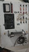
  • Photo of a white experiment board with a small analogue meter, a black schematic plate, stacked terminal posts, resistors, wiring leads and a small DC motor with a cable clamped to it.
    20210923_144502.jpg
    28.9 KB · Views: 186
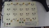
  • Photo of a cream-coloured Fourier Analysis Kit board with rows of capacitor-value switches labelled 5 µF down to 0.0001 µF, binding posts, an ON/OFF switch and a red pushbutton; a printed label reads Fourier Analysis Kit of sine, square and triangle wave.
    20210923_144337.jpg
    37.8 KB · Views: 194
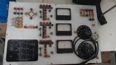
  • Photo of an electrical experiment board with three analogue meters, two rotary dial resistance boxes, patch sockets and a printed panel titled STUDY OF RC CIRCUIT WITH ULTRA LOW FREQUENCY AC (R-C-T).
    20210923_144232.jpg
    55.8 KB · Views: 180
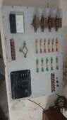
  • Grey lab panel with a black ammeter, four transformers, rows of orange and green terminal sockets, resistors, a small bridge-like resistor network, and a black plate with a circuit diagram.
    20210923_142708.jpg
    26.3 KB · Views: 207
Last edited:
VVS2000 said:
I recently got these electrical experiment boards to do some experiments but I am new to doing experiments with such boards. Can someone help? Thanks in advance
Wow, those are antique! I'm guessing that they did not come with any documentation other than the drawings on them? Were you able to find anything about them by doing a Google search? At least one of them is labeled with a school's Physics department on it, I think.
 
berkeman said:
Wow, those are antique! I'm guessing that they did not come with any documentation other than the drawings on them? Were you able to find anything about them by doing a Google search? At least one of them is labeled with a school's Physics department on it, I think.
Yeah they're associated with rajasthan university but could'nt find anything more than that, these images have reduced in size and clarity after uploading them, I will attach a link to the proper clarity of the images
 
Those look pretty cool. I wish I'd had those when I was young.

I think your first experiment is to investigate each of the components on those boards. What are they supposed to be? Are any of them damaged? How do they work, for example: how much current makes a meter go to full scale; or what is a bridge rectifier? If any have part numbers try to find their component data sheets; for example, how much current can you pass through a diode without damage? What type of capacitors are provided? are they polarized? How much voltage can the tolerate? How much power can each resistor dissipate without damage?

BTW, this isn't just about figuring out what you have. This is a large fraction of what practicing EEs do. Our circuits are full of parts we buy, and we spend lots of time and effort just figuring out how to use what we've bought (reading manufacturer's documents), or how to buy what we need. In the world of analog electronics or fast digital circuits, there is often a lot of time and effort spent characterizing the tricky parts of the system. Often we don't have the data we need for parts we have to use, or that we built ourselves, and so we must experiment to find that data.