How are the connectors on the DC linear actuator utilized in wiring?

Click For Summary

Discussion Overview

The discussion revolves around the wiring and functionality of a 12V DC linear actuator, specifically focusing on the connectors involved and their roles in controlling the actuator's movement. Participants explore the actuator's design, including its use of solenoids, and the implications for its operation in a project requiring bidirectional movement.

Discussion Character

  • Exploratory
  • Technical explanation
  • Debate/contested
  • Experimental/applied

Main Points Raised

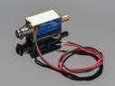
  • One participant describes the actuator as utilizing a magnetic coil and plunger design, likening it to a solenoid, and seeks clarification on the function of its connectors.
  • Another participant suggests measuring the male socket pin to determine if it serves as a ground connector, hypothesizing that the female sockets are for driving the actuator in both directions.
  • Concerns are raised about the actuator's ability to provide push-pull action, with suggestions that a return spring or an additional coil may be necessary for such functionality.
  • Participants inquire about part numbers and datasheets to better understand the actuator's specifications and capabilities.
  • One participant mentions that the actuator is intended to shift a motorcycle transmission, implying it should function in both directions.
  • Another suggests testing the actuator with a 12V power supply to verify its operation, while also requesting resistance measurements between the connectors.
  • Discussion includes links to external resources for similar solenoids and installation guides, though some participants express frustration over the lack of specific information about the actuator in question.
  • There is speculation that the actuator may contain multiple solenoids controlled by three wires, with a possibility of a center return spring.

Areas of Agreement / Disagreement

Participants express differing views on the actuator's design and functionality, particularly regarding its ability to achieve bidirectional movement. There is no consensus on the exact role of the connectors or the internal mechanism of the actuator, leading to ongoing exploration and inquiry.

Contextual Notes

Participants note the absence of part numbers and specific data, which limits the ability to draw definitive conclusions about the actuator's wiring and operation. The discussion relies heavily on assumptions and hypotheses that remain unverified.

Ramok
Messages
7
Reaction score
0
A am working on a project that uses this 12V DC linear actuator. The actuator utilizes a magnetic coil and plunger inner design (I believe this is just a solenoid). This actuator will need to use both directions of movement for the project. In terms of wiring, what do the two female connectors do as well as the male connector?

20230126_111459[1].jpg
20230126_111452[1].jpg
 
Engineering news on Phys.org
Use a multimeter and measure between the male socket pin and the housing. It seems very likely that the pin is a (safety) ground connector. The two female sockets are probably the drive inputs - my guess is +12V applied one way drives the actuator out and +12V applied the other way drives the actuator in. But - those are just my guesses!
 
Can you see a part number on it?
 
  • Like
Likes   Reactions: hutchphd and berkeman
Welcome to PF.

Ramok said:
This actuator will need to use both directions of movement
A solenoid like that is generally only attractive, not repulsive. The higher B-field concentration inside the coil pulls the metal shaft into its interior. In order to get a push-pull action, you would need to use a return spring for the push action, or use another coil that would pull the main metal part of the plunger back into it. Are you sure that solenoid you show is supposed to be capable of the "push" motion? Can you link to its datasheet or provide a manufacturer part number?
 
  • Like
Likes   Reactions: dlgoff and hutchphd
Like this
 

Attachments

  • 412-00.jpg
    412-00.jpg
    30.9 KB · Views: 119
DaveE said:
Can you see a part number on it?
I cannot see a part number
 
berkeman said:
Welcome to PF.A solenoid like that is generally only attractive, not repulsive. The higher B-field concentration inside the coil pulls the metal shaft into its interior. In order to get a push-pull action, you would need to use a return spring for the push action, or use another coil that would pull the main metal part of the plunger back into it. Are you sure that solenoid you show is supposed to be capable of the "push" motion? Can you link to its datasheet or provide a manufacturer part number?
This solenoid is meant to shift a motorcycle transition up and down, so I believe it should have both directions.
 
When it's disconnected, can you easily slide it into any position, or is there some spring tension holding it at one extreme?
 
If you really have no data then you should measure the forward and backward resistance between the three terminals. Make a table and report back...
 
  • Like
Likes   Reactions: berkeman and DaveE
  • #10
Ramok said:
This solenoid is meant to shift a motorcycle transition up and down, so I believe it should have both directions.
Please provide links to the supplier and the product.
 
  • Like
Likes   Reactions: berkeman and hutchphd
  • #11
DaveE said:
When it's disconnected, can you easily slide it into any position, or is there some spring tension holding it at one extreme?
With no power it slides freely without tension.
 
  • #15
berkeman said:
Hmm, yeah, that's very little help. Do you have one? Is there a marking on it for the model number or manufacturer?
I have one and looked all over it. No markings or except for the Pingel logo. I know its not helpful, which is mostly why I posted here maybe someone had more knowledge about this style of solenoid than I do.
 
  • #16
Ramok said:
I have one and looked all over it. No markings or except for the Pingel logo. I know its not helpful, which is mostly why I posted here maybe someone had more knowledge about this style of solenoid than I do.
Do you have a 12V bench power supply? If so, maybe try driving 12V through the two female connectors both ways to see if that fires the solenoid in the push and pull directions. If it doesn't we'll need to figure something else out. BTW, what is the resistance you measure in each of the two directions between the two female input connectors?
 
  • #17
At the moment I don't have access to that power supply or even a multimeter. I will hopefully be able to go test the suggestions you have given me later tonight or tomorrow.

I did find this pdf for installing pingel's kit, I'm not sure if it is any more help you you tho.
https://www.physicsforums.com/file:///C%3A/Users/Rayce/Downloads/Universal%204-Coil%2077401%20&%2077402%20rev06102014%20(1).pdf
 

Attachments

  • #18
The Pingel linear actuator may have two internal solenoids, but with one armature. One solenoid coil would be used to kick up, the other to kick down. Three wires are sufficient to control the two solenoid coils. Maybe there is a centre return spring.

A linear actuator, employing a ball screw, would normally have an external motor. It would also need to return to the mid-position after operation.
 
  • Like
  • Informative
Likes   Reactions: Ramok, Tom.G and berkeman
  • #19
There is a phone number for Pingel on the PDF. Have you tried them?
This solenoid must have multiple coils internally but there are a number of ways one could do this.
 
  • Like
Likes   Reactions: berkeman

Similar threads

  • · Replies 7 ·
Replies
7
Views
3K
  • · Replies 25 ·
Replies
25
Views
2K
  • · Replies 2 ·
Replies
2
Views
2K
  • · Replies 2 ·
Replies
2
Views
3K
  • · Replies 4 ·
Replies
4
Views
2K
Replies
15
Views
3K
  • · Replies 7 ·
Replies
7
Views
4K
Replies
8
Views
2K
  • · Replies 49 ·
2
Replies
49
Views
7K
  • · Replies 28 ·
Replies
28
Views
4K