Discussion Overview
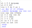
The discussion revolves around finding the DC gain from an AC simulation in LTspice, specifically using a netlist without a schematic. Participants explore methods to derive the DC gain from simulation results and the implications of using decibel (dB) measurements in this context.
Discussion Character
- Technical explanation
- Debate/contested
- Homework-related
Main Points Raised
- One participant expresses uncertainty about how to find the DC gain from the AC simulation results provided in a netlist.
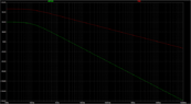
- Another participant suggests that DC gain can be approximated by observing the AC response at low frequencies, where the gain remains constant.
- It is proposed that the DC gain can be derived by changing the '.ac' command to a '.dc' command in LTspice.
- One participant mentions that the constant gain observed in the graph (100 dB) cannot be directly interpreted as gain without further steps.
- Another participant explains that 100 dB can represent voltage gain and suggests converting it to a voltage ratio for clarity.
- There is a discussion about the use of dB to express ratios and the mathematical basis for using 20log for voltage ratios.
- One participant challenges the notion that the professor's approach is flawed, suggesting that the lack of a schematic may be intentional to encourage learning through deciphering the netlist.
Areas of Agreement / Disagreement
Participants express disagreement regarding the necessity and implications of having a schematic. While some believe the professor's approach is misguided, others suggest it may serve an educational purpose. There is no consensus on the best method to derive the DC gain from the given simulation data.
Contextual Notes
Participants note that the lack of a schematic may complicate the understanding of the circuit, and there are unresolved questions about the specific steps needed to accurately determine the DC gain from the provided simulation results.