Discussion Overview
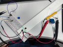
The discussion revolves around the connection and setup of a 4-element strain gauge in a Wheatstone bridge configuration. Participants are exploring the appropriate voltage supply, gauge orientation, and the use of an AD620 amplifier for signal amplification. The conversation includes troubleshooting steps and considerations for proper measurements.
Discussion Character
- Exploratory
- Technical explanation
- Debate/contested
- Mathematical reasoning
- Experimental/applied
Main Points Raised
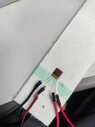
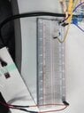
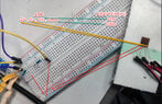
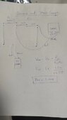
- Some participants suggest connecting the strain gauge to a Wheatstone bridge and applying a voltage to measure the output, while others express uncertainty about the correct setup.
- There are conflicting views on the appropriate voltage supply for the bridge, with some recommending around 1 volt and others suggesting higher voltages for the AD620 amplifier.
- Participants discuss the potential issue of gauge heating and its impact on readings, with suggestions to experiment with different setups.
- Some participants propose using a potential divider to achieve the desired voltage, while others question the user's understanding of basic circuit concepts.
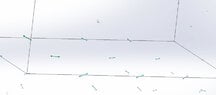
- There are inquiries about the orientation of the strain gauge and its alignment with the principal stress direction, indicating potential issues with measurement accuracy.
Areas of Agreement / Disagreement
Participants express multiple competing views regarding the correct voltage supply and gauge orientation, and the discussion remains unresolved with no consensus on the best approach.
Contextual Notes
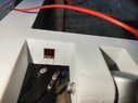
Participants mention limitations in their equipment, such as the inability to set specific voltages on their power supply, and there are unresolved questions about the strain gauge's behavior under different conditions.
Who May Find This Useful
This discussion may be useful for individuals working with strain gauges, those interested in circuit design, and users of Arduino in experimental setups involving sensors.