I getting my homemade DC motor to work (school project)

Click For Summary

Discussion Overview

The discussion revolves around troubleshooting a homemade DC motor for a school project. Participants explore various aspects of the motor's construction, including the materials used for the armature, commutator, and brushes, as well as the arrangement of magnets and the electrical connections. The focus is on identifying issues that prevent the rotor from functioning properly.

Discussion Character

  • Exploratory
  • Technical explanation
  • Debate/contested
  • Homework-related

Main Points Raised

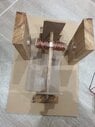
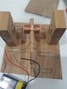
  • One participant describes their motor's construction using copper wire, wood, neodymium magnets, and paper clips, noting that the rotor does not move despite current passing through the wires.
  • Another participant suggests that the rotor should be a single coil with consistent helicity and that the stator magnets should be arranged in a specific orientation.
  • There is a discussion about the necessity of using an iron armature instead of a wooden one, with some participants asserting that an iron armature is essential for proper function.
  • Concerns are raised about the friction in the bearings and suggestions are made to either use an iron armature or modify the wooden bearings to reduce friction.
  • Participants discuss the importance of ensuring the correct polarity of the magnets and the need to reduce the gap between the armature and the magnets for better performance.
  • One participant reports a small force when the motor is jump-started but notes that it does not continue to spin on its own.
  • There are suggestions to check the orientation of the magnets and to use a compass to verify their polarity.

Areas of Agreement / Disagreement

Participants express multiple competing views regarding the materials and construction methods for the motor. There is no consensus on the exact cause of the motor's failure to operate effectively, and various suggestions are offered without agreement on a single solution.

Contextual Notes

Participants mention various construction details, such as the need for soldering connections and the potential impact of the bearings on motor performance. There are unresolved questions about the effectiveness of the current setup and the necessity of specific materials.

Who May Find This Useful

This discussion may be useful for students and hobbyists interested in building or troubleshooting DC motors, particularly in educational settings or DIY projects.

hi8192
Messages
11
Reaction score
4
Thread moved from the technical forums to the schoolwork forums
hi everyone, i need to build a dc motor for my school project. I have used copper wire for the turns (60 turns), wood to build the structure of the armature and commutator. i have used neodymium magnets as my permanent magnets and paper clips as the brushes. I tried using a 9v battery with a clip connector connecting with the brushes but my rotor does not seem to move. I know there is current passing through because the wires heat up but there is no force. I have sanded off the coating on the copper wire that is looped around the commutator but maybe i have to sand more off? could the hot glue i used to assemble my armature be an issue? do i need more turns? I'm really stressed about this and i would appreciate any suggestions on how i can get it to work. thank you!
here is a photo of my model:
 

Attachments

  • fcaa99ce-df1f-486c-aa64-ce4c3444b557.jpg
    fcaa99ce-df1f-486c-aa64-ce4c3444b557.jpg
    42.2 KB · Views: 233
Physics news on Phys.org
There is no force at all on the rotor when energized? The rotor should be a single coil (all the same helicity) and the stator magnets arranged |NS|(rotor)|NS| .
 
  • Like
Likes   Reactions: hi8192
hutchphd said:
There is no force at all on the rotor when energized? The rotor should be a single coil (all the same helicity) and the stator magnets arranged |NS|(rotor)|NS| .
yeah there is 0 force, i even tried giving it a kickstart to get it moving but it doesn't seem to work. I'm not sure what you mean by single coil but i have arranged the magnets as you've suggested.
 
I mean that the coil has the same helicity all the way across so one end is N and the other S until the electricity is commutated and it switches. The iron core is continuous for stronger magnet.
 
  • Like
Likes   Reactions: hi8192
hi8192 said:
... , wood to build the structure of the armature and commutator. ...
What is the coil wound on? An iron or a wooden armature?

The coils look to be wound in the right sense, but I cannot see the cross-over between the coils.

Positively identify the poles of the magnets, mark them clearly with N and S.
Use a magnetic compass, or another magnet, to determine if current flows through the coil when you connect it.
 
  • Like
Likes   Reactions: hutchphd and hi8192
Welcome to PF. :smile:

hi8192 said:
I have sanded off the coating on the copper wire that is looped around the commutator but maybe i have to sand more off?

What does that mean? Usually you would solder the two inner ends of the coils to the two pieces of the commutator, not try to make Ohmic contact between the inner ends of the coils and the commutator. Can you post pictures of the motor more disassembled so we can check it? Thanks.
 
  • Like
Likes   Reactions: hi8192
Baluncore said:
What is the coil wound on? An iron or a wooden armature?

The coils look to be wound in the right sense, but I cannot see the cross-over between the coils.

Positively identify the poles of the magnets, mark them clearly with N and S.
Use a magnetic compass, or another magnet, to determine if current flows through the coil when you connect it.
i wound them around a wooden armature - i will clarify the magents and assess what you've suggested, thanks!
 
  • Like
Likes   Reactions: berkeman
berkeman said:
Welcome to PF. :smile:
That does that mean? Usually you would solder the two inner ends of the coils to the two pieces of the commutator, not try to make Ohmic contact between the inner ends of the coils and the commutator. Can you post pictures of the motor more disassembled so we can check it? Thanks.
the youtube video i was following said to sand off the enamel so i did lmao - i'll post the disassembled pictures in a few hours when i get home
 
hi8192 said:
i wound them around a wooden armature
There is your problem. An iron armature is needed.
I wound my first motor with button sewing thread, not copper wire.
 
  • Like
Likes   Reactions: hutchphd and hi8192
  • #10
Baluncore said:
I wound my first motor with button sewing thread, not copper wire.
How did that work out for you...? :smile:
 
  • #11
berkeman said:
How did that work out for you...?
There was no PF at the time, so I had to work it out for myself. It taught me to think and focus, and probably determined my life's trajectory. 15 years later, over morning coffee in the University Science Labs, an electronics tech confirmed he had done the same, after reading the same book. I have often wondered if we were the only two, or what happened to the thousands of others in that position.
 
  • Like
  • Haha
Likes   Reactions: hutchphd and berkeman
  • #12
Baluncore said:
There is your problem. An iron armature is needed.
I wound my first motor with button sewing thread, not copper wire.
oh i hadn't even thought about an iron armature - do u have any ideas how i would make/buy one?
 
  • #13
I would use an iron bolt with the head at one end, and a nut at the other end to balance it.
Perhaps if you gave us a link to the YouTube video, we could do it their way.
 
  • Like
Likes   Reactions: hi8192
  • #14
Baluncore said:
I would use an iron bolt with the head at one end, and a nut at the other end to balance it.
Perhaps if you gave us a link to the YouTube video, we could do it their way.
this is the video i followed
 
  • #15
The bearings at the ends of your motor are high friction. If you use a wooden armature, you will need to drill the ends of the shaft and use a pin or wire as the support. That is shown at 30 seconds in the video. With the bearings you have, you would need an iron armature, or to grease the wooden bearings with margarine. You might also reduce the clearance between the magnets and the coil ends.
From where you are now, it is probably easiest to use the pin bearings that have low friction.
 
  • Like
Likes   Reactions: hutchphd and hi8192
  • #16
Baluncore said:
The bearings at the ends of your motor are high friction. If you use a wooden armature, you will need to drill the ends of the shaft and use a pin or wire as the support. That is shown at 30 seconds in the video. With the bearings you have, you would need an iron armature, or to grease the wooden bearings with margarine. You might also reduce the clearance between the magnets and the coil ends.
From where you are now, it is probably easiest to use the pin bearings that have low friction.
ahh this is very helpful thank you soo muchh - i'll try it out and hopefully it'll work
 
  • #17
Baluncore said:
The bearings at the ends of your motor are high friction. If you use a wooden armature, you will need to drill the ends of the shaft and use a pin or wire as the support. That is shown at 30 seconds in the video. With the bearings you have, you would need an iron armature, or to grease the wooden bearings with margarine. You might also reduce the clearance between the magnets and the coil ends.
From where you are now, it is probably easiest to use the pin bearings that have low friction.
okay so i shortened my dowel and armature to reduce the mass, and used a thinner coil (0.4mm) for the turns (80), i also took your suggestion to use the pin bearings but the motor still isn't working. i'd appreciate any more suggestions you have. here's an updated pic:
 

Attachments

  • fdb5a860-61b2-4364-9989-b5e05178f5a9.jpg
    fdb5a860-61b2-4364-9989-b5e05178f5a9.jpg
    37.7 KB · Views: 195
  • #18
Have you checked the orientation of your magnets ?
Use a magnetic compass or another magnet to sense the polarity.
You need to reduce the gap between the armature ends and the magnets.
 
  • #19
Baluncore said:
Have you checked the orientation of your magnets ?
Use a magnetic compass or another magnet to sense the polarity.
You need to reduce the gap between the armature ends and the magnets.
the magnets are definitely attracted to each other - i tried determining the exact polarity using the phone compass but it didn't work (kept pointing to west) and i don't have a physical compass so i think ill borrow a magnet from school tomorrow and test it out. i did also reduce the gap but that just led to the magnets being pulled towards each other
 
  • #20
there is a small force! when i give it a jump start, the commutator rotates a bit on its own but it won't continue. i'd upload a video but it won't let me
 
  • #21
A video will NOT help diagnose the problem.
You need to get the magnets closer to the armature, even if you have to hold them down.

Does it spin by hand, or are the bearings not free to turn?

A small toy magnetic compass can be used to test the polarity of the magnets. If you remove the magnets, it can also be used to sense if current is flowing through the wire.
 
  • Like
Likes   Reactions: hi8192
  • #22
Good. I notice that the paperclip brushes are not exactly opposite (180 degrees). For smooth operation both the bushes and the commutator should be opposed by 180 (and offset as suggested). Also if you have extra magnets you could stack two at each stator.
 
  • Like
Likes   Reactions: hi8192
  • #23
i stuck the magnets closer to armature with hot glue and when i gave it a big enough force it actually spun for around 15 secs! I'm going to align the paperclips at 180 degrees as suggested, determine the polarity and hope that it continues to work otherwise i'll buy some more magnets to stack. thank you so much! I'm so relieved
 
  • Like
Likes   Reactions: Delta2, hutchphd and Baluncore
  • #24
I can't be sure from the photograph but is the wire you are using insulated? Sorry if this is telling my grandmother how to suck eggs but I have come across many failed motors that were wound with uninsulated wire. The wire I can see could be just copper or it could be enamelled with a coppery coloured enamel. Then the ends need to be well cleaned of enamel to make a good contact with the 'commutator.
 
  • Like
Likes   Reactions: hi8192
  • #25
Baluncore said:
I wound my first motor with button sewing thread, not copper wire.

berkeman said:
How did that work out for you...? :smile:

This thread, and the exchange quoted above, gave me a strange sense of nostalgia and deja vu. A memory surfaced from my subconscious mind that I had not thought of for nearly 50 years. As a schoolboy I got to read the book "Energy" by Mitchell Wilson, from Time-Life Books. There were instructions on building a paperclip motor, which I tried unsuccessfully to implement.

I just dug up the book on archive.org, https://archive.org/details/energywils00wils/mode/2up

paperclip_motor.png


More recently I helped my niece build a brushless "pulse motor" that worked pretty well. It used a home-made magnetic switch to pulse the current at the right moment during each revolution --

 
  • Love
Likes   Reactions: Delta2
  • #26
Swamp Thing said:
This thread, and the exchange quoted above, gave me a strange sense of nostalgia and deja vu. A memory surfaced from my subconscious mind that I had not thought of for nearly 50 years. As a schoolboy I got to read the book "Energy" by Mitchell Wilson, from Time-Life Books. There were instructions on building a paperclip motor, which I tried unsuccessfully to implement.

I just dug up the book on archive.org, https://archive.org/details/energywils00wils/mode/2up

View attachment 304764

More recently I helped my niece build a brushless "pulse motor" that worked pretty well. It used a home-made magnetic switch to pulse the current at the right moment during each revolution --


Great post. A lot of these kitchen table projects actually require an inherent knowledge of Science and experimental savvy (which even venerable PF members started off without. For instance, a young @Baluncore - bless'im) - or a lot of luck.
 

Similar threads

  • · Replies 4 ·
Replies
4
Views
2K
  • · Replies 10 ·
Replies
10
Views
5K
  • · Replies 19 ·
Replies
19
Views
5K
  • · Replies 41 ·
2
Replies
41
Views
7K
  • · Replies 16 ·
Replies
16
Views
4K
  • · Replies 13 ·
Replies
13
Views
3K
Replies
13
Views
4K
Replies
21
Views
2K
  • · Replies 1 ·
Replies
1
Views
3K
  • · Replies 10 ·
Replies
10
Views
3K