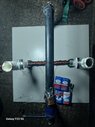
The magnets are backwards. The N pole on one should be facing the S pole on the other one.
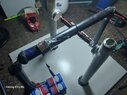
Without power applied, inspect the brush/armature alignment to make sure that both brushes never contact the same armature segment during a complete rotation.
By the way, a simple 2-pole motor like this will NOT start on its own! You will have to give it a good spin by hand to get it running.
The batteries are connected in series which means their voltages add but their current capability remains the same as one battery. I would expect this motor to require a rather high current to operate. I suggest the batteries be connected in parallel, all the "+" connected together and all the "-" connected together. The result will be 9V but with four times the current capability.
Better yet, take the advice of
@tech99 in post #2 and use 2 to 4 "D" cells in series; they are more difficult to connect to though.
You might have to make a battery holder by nailing some metal strips to a piece of wood, then use rubber bands to hold the strips in contact with each battery. Much easier if you contact each battery individually, they won't stay in line if you place them head-to-tail as in a flashlight!
By the way, if you do not have a voltmeter to test the 9V batteries, here is a simple test. Using a single 9V battery,
briefly touch the contacts to the top of your tongue just behind the tip.
a) If you sorta wish you hadn't done that, the battery is new
b) If you feel a substantial tingling and maybe a slight sour taste, it's "Usable"
c) Mild tingling, probably not much good for anything
d) No or very slight tingling, or an acid taste, dead
If the suggestions from everyone so far do not get it running, here is another simple test to help track down the problem.
1) Find a couple somethings, maybe screwdriver or plyers, made of Iron or Steel.
We want them NOT magnetized, so bring them in contact with each other then gently separate them. If they feel like they stick together then one or both of them are magnetized. Try other items from your tool box, or even some nails, until you find two Iron or Steel things that don't attract each other. They don't have to be the same shapes.
2) With no power to the motor, position the motor armature so the bolt is vertical, farthest away from the magnets. Now bring one of the Iron/Steel items to one end of the bolt. If it is attracted that means the armature is magnetized; remember how strong the attraction is, you will need it for comparison in the next step. Not to worry whether magnetized or not right now, it could have been magnetized when connected to the battery or just by being close to the permanent magnets.
3) Now connect the battery and rotate the armature a little if needed to get current to flow thru the armature winding.
4) Bring the
second piece of Iron/Steel to one end of the bolt. It should be attracted much more strongly that the test in step 2), above.
If there is the same attraction from step 2) and from step 4) then either there is no current flowing thru the winding OR the winding is wound incorrectly; it should be all wound in the same direction; that is looking at the same end of the bolt, all the winding should be either clockwise or counter-clockwise.
Well, it's past my bedtime, hope this helps.
Have Fun!
Cheers,
Tom
p.s. Please keep us updated on your progress