Engineering Maximum normal stress and shear stress

Click For Summary
To determine the external reactions at points A and B, additional relationships beyond the single equation for vertical forces (VA and VB) are needed. After calculating these reactions, the external moment can be established, allowing for the creation of moment diagrams for each cross-section to identify the maximum moment. The maximum normal stress can be calculated using the formula σ = -My/I once the maximum moment is known. Additionally, exploring the general formula for beam displacement can help impose a specific deflection condition, such as v(4) = -0.5 mm, to solve for VA, VB, and MA. The discussion also raises a question about the end deflection if support B were absent.
Moara
Messages
43
Reaction score
5
Homework Statement
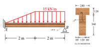
A cantilever with elasticy modulus (##E = 13 \ GPa##) is subjected to the distribution of forces as in figure. The cross section T shaped is indicated in the figure. The moment of inertia with respect to the centroidal axis ##z## is ##1496.45 \cdot 10^6 \cdot mm^4##. In the absence of the distribution of forces, there is a lack of ##0.5 mm## between the bean and the mobile support. Knowing that the bean touches the support with the load distribution, find:
1) The maximum normal stress
2) The value of the maximum shear stress in the body
3) The deflection in the middle of the bean
Relevant Equations
##\sum{F_y} = 0##, ##\sum{M} = 0##
First, I am trying to find the external reactions in A and B, but I have only one equation relating ##V_A## and ##V_B##, what other relation could I use ?
Once I find the reactions, I can find the external moment as well. Then, I may draw the diagram of moments in each cross section and then find the maximum Moment. Using that ##\sigma = -My/I## I can find the maximum normal stress.
 

Attachments

  • QUESTION.png
    QUESTION.png
    19.4 KB · Views: 143
Last edited:
Physics news on Phys.org
Indeed, maybe we can try to find the general formula for the displacement of the beam and then impose that ##v(4) = -0.5 mm##. With that, I think we may find ##V_A, V_B, M_A## and find the diagram of moments, to find its maximum value
 
What would the end deflection be if B was not there?
 
Greetings to all, I am writing with a question regarding graph generation in LTSpice. I am using LTSpice XVII and am trying to plot AM-AM and AM-PM characterization for a power amplifier, but I haven't been successful yet, likely due to my lack of practice with this specific analysis. I have been using a square wave input at 8.2 MHz as the voltage waveform for my power amplifier. It is said that for a switching amplifier like Class-D, the AM-AM / AM-PM (amplitude-to-amplitude and...
Thread 'How do I determine the resistance for RLC low pass filter?'
Hi, I am trying to build a RLC low pass filter that atenuates the frequency below 4500 Hz. However, I have encountered some problem when choosing the correct R to work with. Here is the Circuit Here is the original sound. Here is my code in Matlab function Vout = myFilterCircuit(Vin,h) n_V = length(Vin); f_7 = 4470;; % Undesired frequency h_7 = h; % delta time % These are for the constant and initialization of the variables t_7 = 0:h_7:(n_V-1)*h_7; % This is the independent variable...

Similar threads