artis
- 1,479
- 977
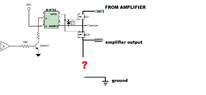
Hello, as you can see in the attached image I have an opamp driving a BJT transistor that controls the power through a isolated mosfet driver IC that drives 2 series (back to back) N fets performing the duty of a solid state amplifier output relay.
Now my concern is this. In case the output to speaker has high current but the safety needs to disconnect the amplifier, the mosfets will be disconnected but unlike a mechanical relay there will be no arc and the current termination will be sharp and abrupt which might cause an inductive flyback voltage spike.
My idea to eliminate this is to have a separate switching element that is normally open but every time the output mosfet switches OFF the other switch closes or turns ON, this would short circuit the speaker output terminals through the switch. I would add some 8 ohm or larger resistor in series with the switch for current limitation and dissipation.
The questions is how to best implement such a switch and wire it with the existing circuitry.
Maybe there are some better solutions like reverse polarity diodes from PSU + rail to output and output to - rail or some other method?
I was originally thinking about a thyristor, aka TRIAC or GTO in a "crowbar" style output shunt.
All in all I am favoring an easy to implement and simple solution in this case but one that is reliable
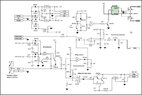
PS. I also attached the full protection board schematic for those interested
Now my concern is this. In case the output to speaker has high current but the safety needs to disconnect the amplifier, the mosfets will be disconnected but unlike a mechanical relay there will be no arc and the current termination will be sharp and abrupt which might cause an inductive flyback voltage spike.
My idea to eliminate this is to have a separate switching element that is normally open but every time the output mosfet switches OFF the other switch closes or turns ON, this would short circuit the speaker output terminals through the switch. I would add some 8 ohm or larger resistor in series with the switch for current limitation and dissipation.
The questions is how to best implement such a switch and wire it with the existing circuitry.
Maybe there are some better solutions like reverse polarity diodes from PSU + rail to output and output to - rail or some other method?
I was originally thinking about a thyristor, aka TRIAC or GTO in a "crowbar" style output shunt.
All in all I am favoring an easy to implement and simple solution in this case but one that is reliable
PS. I also attached the full protection board schematic for those interested