Jamie1234
- 3
- 0
- TL;DR
- Corroborating the output of a trivial equation
Hello.
I would like to replicate the plot (a figure) provided in an example. The example is presented in a journal paper and shows the calculation for the inductance of a motor with known torque and angular speed.
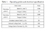
Below is the figure, and the table of parameters provided in the paper


Border 2 in the above figure is given by equation 10, below:

Calculating the inductance for the values of magnetic flux 0.24:0.05:0.260 as shown in the Figure, we obtain the values:
La_10 = 0.0000 + 0.0115i, 0.0000 + 0.0118i, 0.0000 + 0.0120i, 0.0000 + 0.0123i and 0.0000 + 0.0126i
Am I going mad?? :/ .
Code snippet:
N_a = 1500 % Speed [RPM]
Ta = 10 % Torque [Nm]
I_am = 20 % Armature current limit [A]
V_om = 100 % induced voltage limit [V]
V_lim = 160 % Voltage limit of inverter [V]
Flux_PM = [0.240:0.005:0.260]
La_10 = 1 / I_am * sqrt((V_om/N_a)^2 - Flux_PM.^2)
plot(Flux_PM, La)
I would like to replicate the plot (a figure) provided in an example. The example is presented in a journal paper and shows the calculation for the inductance of a motor with known torque and angular speed.
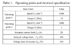
Below is the figure, and the table of parameters provided in the paper
Border 2 in the above figure is given by equation 10, below:
Calculating the inductance for the values of magnetic flux 0.24:0.05:0.260 as shown in the Figure, we obtain the values:
La_10 = 0.0000 + 0.0115i, 0.0000 + 0.0118i, 0.0000 + 0.0120i, 0.0000 + 0.0123i and 0.0000 + 0.0126i
Am I going mad?? :/ .
Code snippet:
N_a = 1500 % Speed [RPM]
Ta = 10 % Torque [Nm]
I_am = 20 % Armature current limit [A]
V_om = 100 % induced voltage limit [V]
V_lim = 160 % Voltage limit of inverter [V]
Flux_PM = [0.240:0.005:0.260]
La_10 = 1 / I_am * sqrt((V_om/N_a)^2 - Flux_PM.^2)
plot(Flux_PM, La)
Attachments