Questions about Circuit Models of Transmission Lines

  • #1
TL;DR Summary
Can someone explain lumped element circuit model of transmission lines please?
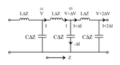
This is for my graduate EM Theory class. My background is physics/optics, so I was able to understand when we solved maxwells eqs. for waves propagating between parallel conducting plates, but that lead into the lumped element circuit model of transmission lines which I don't understand. I've attached the figure we used. My question is why does the circuit look this way? Do the two horizontal wires represent the two parallel plates, or is the top one the transmission line and the bottom one ground? And how do we know that the RLC components should be arranged in this way instead of some other way?
 

Attachments

  • circuit.png
    circuit.png
    8.3 KB · Views: 36

Answers and Replies

  • #2
The model you show is of a transmission line over a ground plane.
The line has inductance per unit length, and capacitance to ground per unit length.
Drawn as a ladder network, it makes a low-pass filter, with a very high cutoff frequency.
https://en.wikipedia.org/wiki/Transmission_line#Telegrapher's_equations

From the lumped model, you can determine the characteristic impedance and the velocity factor. Your lumped model has no resistance, so it is an ideal lossless line.
 
  • #3
The model you show is of a transmission line over a ground plane.
The line has inductance per unit length, and capacitance to ground per unit length.
Drawn as a ladder network, it makes a low-pass filter, with a very high cutoff frequency.
https://en.wikipedia.org/wiki/Transmission_line#Telegrapher's_equations

From the lumped model, you can determine the characteristic impedance and the velocity factor. Your lumped model has no resistance, so it is an ideal lossless line.
So the top wire represents the transmission line and the bottom is ground? And why would a transmission line act as a lo pass filter?
 
  • #4
And why would a transmission line act as a lo pass filter?
Because a transmission line has a cutoff frequency, by virtue of the fact that it has series inductance, with parallel capacitance, distributed over its length.
 
  • Like
Likes anorlunda and Averagesupernova
  • #5
The lumped element circuit has a cut off frequency but a real line is continuous and does not. We need more LC sections to raise the cut off frequency of this equivalent circuit.
 
  • #6
Leon Brillouin wrote a beautiful little book called Wave Propagation in Periodic Structures that covers transmission lines from a physics perspective before moving on to waves (acoustic and optical) in crystals. With your background, it should be an enlightening read.
 
Last edited:
  • #7
So the top wire represents the transmission line and the bottom is ground?
What you show is the model for an unbalanced transmission like, like coax cable. The lumped model for balanced transmission lines (like twisted pair or twin-lead cable) would have inductors in the lower/return leg as well.

The Characteristic Impedance ##Z_0## of a Transmission Line includes the inductance per unit length and the capacitance per unit length, so for a lossless TL that is all you need to include in the lumpted model. Then all you have to decide is how fine you want that model to be per unit length (per meter, for example), based on the frequencies that you want to model propagating down that TL.

A better model includes the loss terms, because if you are trying to match a transmit impedance and a termination impedance to the TL, the loss terms and their effect on ##Z_0(f)## can be significant. In the twisted pair IoT world that I work in, this affects communication datarates in the 100kHz range, but not in the 10MHz range, for example.

1655073433170.png

https://en.wikipedia.org/wiki/Characteristic_impedance
 

Suggested for: Questions about Circuit Models of Transmission Lines

Replies
5
Views
773
Replies
20
Views
1K
Replies
2
Views
675
Replies
10
Views
1K
Replies
6
Views
676
Replies
6
Views
523
Replies
2
Views
460
Replies
2
Views
1K
Back
Top