Homework Help Overview
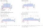
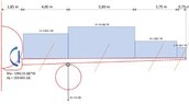
The discussion revolves around analyzing shear and moment lines from a free body diagram (FBD) involving distributed forces, specifically related to the load distribution on the half-wing of an airliner.
Discussion Character
- Exploratory, Assumption checking, Problem interpretation
Approaches and Questions Raised
- Participants discuss the visibility of the posted FBD and the original poster's attempt at identifying shear and moment lines. There are inquiries about the problem text and the approach to determining shear and moment functions, with some questioning the necessity of working from the wingtip to the wing root.
Discussion Status
The discussion is ongoing, with participants seeking clarification on the problem statement and exploring different approaches to the analysis. Some guidance has been offered regarding the direction of analysis, but no consensus has been reached on the best method to proceed.
Contextual Notes
Participants note that the original poster's teacher suggested that starting from the wing root might be easier than the proposed method of starting from the wingtip, indicating a potential assumption about the preferred approach.