Simple bending moment calculation

4 replies · 3K views · last reply
Wilson123
Messages
58
Reaction score
2
Hi,

Really need some help with figuring out the max bending moment in the diagram shown below (I'm aware this is extremely simple but time and stress appear to have the better of me, so any help is appreciated)
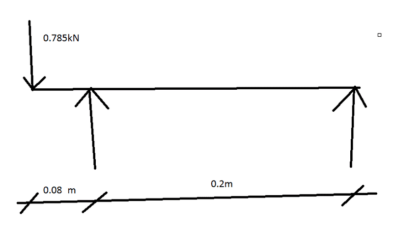
Beam diagram with a downward point load of 0.785kN at the left end, two vertical support reactions at the left and right ends, and dimensions 0.08 m and 0.2 m marked along the bottom.


I think I've worked out the reactions at each support by doing m=wL as the following

0.785 x 0.08 = 0.63
0.785 x 0.28 = 0.22

I'm also aware that I could be completely wrong with what I've just put above.

SOS
 
The beam would probably just tip over with the forces acting in the directions shown .

We need to understand the actual loading system more clearly before calculating bending moments .

Can you post a sketch showing the actual mechanical assembly that your line drawing represents ?
 
I don't think the reactions are correct. As drawn, ΣM = 0 = 0.2R + 0.785(0.08) : R = - 0.314 kN : The "-" sign simply implies you have the right reaction, R, acting the opposite direction. ΣF = 0 = - 0.785 - 0.314 + L : The left reaction, L = 1.099 kN : Given the reactions you should be able to calculate the moment.
Draw shear and moment diagrams.
 
  • Like
Likes   Reactions: Wilson123
Vector1962 said:
I don't think the reactions are correct. As drawn, ΣM = 0 = 0.2R + 0.785(0.08) : R = - 0.314 kN : The "-" sign simply implies you have the right reaction, R, acting the opposite direction. ΣF = 0 = - 0.785 - 0.314 + L : The left reaction, L = 1.099 kN : Given the reactions you should be able to calculate the moment.
Draw shear and moment diagrams.

Thanks a lot for your help.