@ntetlow
I might be an idea to find the source of oscillation in your OP model. Is the same oscillation present in the Advanced_Amplifier_0.asc that I attached to post 7 ?
The Advanced Amplifier is a learning exercise, not a practical optimised audio circuit.
One problem with Audi_amp_bjt-1.asc is that the feedback is taken from the second last stage, not from the output. Another is that, to reduce crossover distortion, the output stage has a quiescent current of 800 mA, without any current limit to prevent the catastrophic thermal runaway. You need a checklist of parameters to verify, so when you optimise a design, you do not end up with something like 800 mA quiescent in the output stage.
ntetlow said:
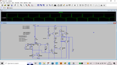
In the mirror circuit the collector currents of Q1 and Q2 are 180 degrees out of phase whereas in the advanced amp circuit they are not. Any ideas why?
The collector currents in the mirror should be in phase. The collector currents in the differential pair should be out of phase. You must be careful how you specify and measure currents because currents can be reversed by reversing a component.
Here is an alternative schematic that operates in class-A up to 5 mA output, then switches on one half of the class-B circuit for higher loads. The base current is balanced to reduce offset voltage. It is not optimised, and was designed to test alternative subcircuits to the Advanced Amplifier.