Supporting a trapezoid between two wedges

  • Thread starter Thread starter Tom Hammer
  • Start date Start date
  • Tags Tags
    Trapezoid
Click For Summary
The discussion revolves around analyzing the forces acting on a trapezoid positioned between two wedges, focusing on the normal and frictional forces on both sides. Calculations indicate that the normal forces (Nr and Nl) and frictional forces (Fr and Fl) are derived from the angles of the wedges, specifically using sine functions. Participants express difficulty in creating a coherent force diagram for the trapezoid, particularly at the surfaces of the wedges. Suggestions include considering only the forces acting perpendicularly to the surfaces and using vector addition to achieve equilibrium. The conversation emphasizes the importance of visualizing these forces to understand the system's stability.
Tom Hammer
Messages
12
Reaction score
2
Homework Statement
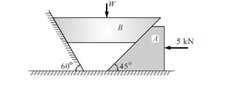
Find the weight W that can be supported by the applied force of 5 kN. Mu = .25 at all surfaces
Relevant Equations
F = mu N, where mu = coefficient of static friction, N = normal force
Let Nr = normal force on the right side of the trapezoid B and Fr = the force of friction on the right side of B.
Let Nl = normal force on the left side of B and Fr = the frictional force on the left surface of B

so Nr = 5 sin45 and Fr = 5 sin45 =
and Nl = 5 sin 60, Fl = 5 sin 30.
 

Attachments

  • 3D280A4F-37D1-426C-9547-6A392149D2CF.jpeg
    3D280A4F-37D1-426C-9547-6A392149D2CF.jpeg
    16.7 KB · Views: 136
Physics news on Phys.org
All surfaces would include the underside of A.
Consider balance of forces on A and balance of forces on B.
 
Yes, thank you. But I am having trouble drawing a force diagram which makes sense at the two surfaces of B.
 
Tom Hammer said:
Yes, thank you. But I am having trouble drawing a force diagram which makes sense at the two surfaces of B.
 
Tom Hammer said:
Yes, thank you. But I am having trouble drawing a force diagram which makes sense at the two surfaces of B.
Not sure why. What forces act on B?
What forces act on A?
If the system slips, can it do so without sliding at all contact surfaces?
 
Tom Hammer said:
Yes, thank you. But I am having trouble drawing a force diagram which makes sense at the two surfaces of B.
Why do you find it difficult?
Forgetting for a moment about block A, only three forces acting perpendicularly to each of the top and side surfaces of B are needed to keep in equilibrium.
Try a vectorial addition of those forces, which should form a triangle.
 
Thread 'Correct statement about size of wire to produce larger extension'
The answer is (B) but I don't really understand why. Based on formula of Young Modulus: $$x=\frac{FL}{AE}$$ The second wire made of the same material so it means they have same Young Modulus. Larger extension means larger value of ##x## so to get larger value of ##x## we can increase ##F## and ##L## and decrease ##A## I am not sure whether there is change in ##F## for first and second wire so I will just assume ##F## does not change. It leaves (B) and (C) as possible options so why is (C)...

Similar threads

  • · Replies 25 ·
Replies
25
Views
2K
  • · Replies 95 ·
4
Replies
95
Views
6K
  • · Replies 7 ·
Replies
7
Views
2K
Replies
46
Views
4K
  • · Replies 7 ·
Replies
7
Views
4K
  • · Replies 1 ·
Replies
1
Views
2K
  • · Replies 42 ·
2
Replies
42
Views
4K
  • · Replies 4 ·
Replies
4
Views
2K
  • · Replies 2 ·
Replies
2
Views
1K
Replies
1
Views
5K