Transimpedance Operational Amplifier Simulation circuit help
- Context: Engineering
- Thread starter CNC101
- Start date
Join the discussion
Ask a follow-up here, or get your own question answered by working scientists, mathematicians and engineers — people, not an autocomplete.
Real named experts · corrections over time · the nuance an AI answer skips
47 replies · 12K views
- 9,253
- 1,080
With 1nA of input current, what does your formula predict the output to be? Try it with a few μA.
CNC101
- 30
- 0
With LTspice and a precision operational amplifier model, I have -100.088mV which I think is close enough. Simetrix required a voltage controlled voltage source to create ideal opamp conditions which just got confusing.
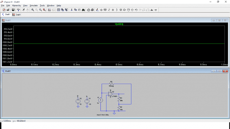
That result is almost exactly right if you don't make a numerical approximation simplifications in the expression for K. An exact value for K would yield 100.09 mV for the output voltage.CNC101 said:With LTspice and a precision operational amplifier model, I have -100.088mV which I think is close enough. Simetrix required a voltage controlled voltage source to create ideal opamp conditions which just got confusing.
CNC101
- 30
- 0
Could you explain what you mean by Numerical approximation simplification, cheers :)
In post #28 you wrote:CNC101 said:Could you explain what you mean by Numerical approximation simplification, cheers :)
CNC101 said:Ok, (-I*Rf-Vout)/R1+(-I*Rf-0)/R2-I= 0 transposes as Vout=-I*Rf(R1/R2+1) to which I= 1nA.
Which is true if you've made the assumption that ##\frac{(R_1 + R_2)}{R_2} R_f >> R_1##, which is a pretty good approximation in this case.
The exact expression is:
##V_{out} = -I \left[ \frac{(R_1 + R_2)}{R_2} R_f + R_1 \right]##
CNC101
- 30
- 0
Well my exact expression was -I(R1(Rf/R2)+1)+R)=V Which gave me 0.9991nA which on the simulation, Vo is shy by just 0.002mV compared to 0.09mV!
Rafeng404
- 17
- 0
Hi guys,
Just thought I would chime in in case as a semi novice like me is reading this thread and to make sure there is nothing wrong with what I have done or if there is a situation where it would be none sense. Hopefully one of you clever lads will be able to put me right.
I got the 1nA just from doing ohms law. We know there is -0.1V across R1 and R2 so R1 must drop -0.09V and R2 must drop -0.01V. We can also agree that R2 is in parallel with RF which also much have the -0.01V volt drop. There for I=0.01/10*10^6 = 1*10^9. Then if you transpose the Vout= -Rf/Rin*Vin formula and substitute Rf*(R1+R2)/Rf+(R1+R2) for Rf and put Rin as 1 (this was me using half educated reason because 0 would bugger the whole thing up) you get 1.01*10^-6 V for the input voltage which I think was mentioned earlier.
Did I get lucky here? or is that a reasonable way to do it? because If I am honest I haven't done your methods for years and couldn't be arsed having to re learn it haha.
Cheers
Just thought I would chime in in case as a semi novice like me is reading this thread and to make sure there is nothing wrong with what I have done or if there is a situation where it would be none sense. Hopefully one of you clever lads will be able to put me right.
I got the 1nA just from doing ohms law. We know there is -0.1V across R1 and R2 so R1 must drop -0.09V and R2 must drop -0.01V. We can also agree that R2 is in parallel with RF which also much have the -0.01V volt drop. There for I=0.01/10*10^6 = 1*10^9. Then if you transpose the Vout= -Rf/Rin*Vin formula and substitute Rf*(R1+R2)/Rf+(R1+R2) for Rf and put Rin as 1 (this was me using half educated reason because 0 would bugger the whole thing up) you get 1.01*10^-6 V for the input voltage which I think was mentioned earlier.
Did I get lucky here? or is that a reasonable way to do it? because If I am honest I haven't done your methods for years and couldn't be arsed having to re learn it haha.
Cheers
How do you know that? There's a junction between R1 and R2 where there's a third connection (to Rf), and you can't make the assumption that it doesn't interfere with the potential drop ratio without justification. In the case of the given problem with the given component values it is possible to make such a justification, but if those values had been different it might not have been the case.Rafeng404 said:We know there is -0.1V across R1 and R2 so R1 must drop -0.09V and R2 must drop -0.01V.
If you submitted your working for marking without providing such a justification, you'd very likely lose points.
Rafeng404
- 17
- 0
gneill said:How do you know that? There's a junction between R1 and R2 where there's a third connection (to Rf), and you can't make the assumption that it doesn't interfere with the potential drop ratio without justification. In the case of the given problem with the given component values it is possible to make such a justification, but if those values had been different it might not have been the case.
If you submitted your working for marking without providing such a justification, you'd very likely lose points.
Thank you for your reply, just so that I understand you correctly, in this case, as we know all the values it is ok to do what I did?
Rafeng404
- 17
- 0
Will do, thank you.
dave pallamino
- 4
- 0
Hi All,
My attempt is a little different, could any of you guys confirm I've gone about this one the right way?
Using KCL at V-
I=(0-Vx)/Rf
Vx=-I*Rf
Using KCL at Vx
((Vx-Vout)/R1)+(Vx/R2)=0
(R2*Vx)-(R2*Vout)+(R1*Vx)=0
Vout=(R1+R2/R2)Vx
Vout=-(R1+R2/R2)I*Rf
Vout=-kI
k=(R1+R2/R2)Rf
I=-((Vout*R2)/((R1+R2)Rf))
I=-((0.1*(10k))/((90k+10k)10M))=-1nF
Any advice would be greatly appreciated...Thanks!
My attempt is a little different, could any of you guys confirm I've gone about this one the right way?
Using KCL at V-
I=(0-Vx)/Rf
Vx=-I*Rf
Using KCL at Vx
((Vx-Vout)/R1)+(Vx/R2)=0
(R2*Vx)-(R2*Vout)+(R1*Vx)=0
Vout=(R1+R2/R2)Vx
Vout=-(R1+R2/R2)I*Rf
Vout=-kI
k=(R1+R2/R2)Rf
I=-((Vout*R2)/((R1+R2)Rf))
I=-((0.1*(10k))/((90k+10k)10M))=-1nF
Any advice would be greatly appreciated...Thanks!
Michael Neo
- 49
- 3
Is I = +1nF or -1nF?
Michael Neo
- 49
- 3
gneill said:The exact expression is:
##V_{out} = -I \left[ \frac{(R_1 + R_2)}{R_2} R_f + R_1 \right]##
When I substitute 0.1 V for Vout and solve for I.
The result is, I = -1/1,900,000 A
I do not think this is the correct answer.
The Electrician
Gold Member
- 1,402
- 210
dave pallamino said:Hi All,
My attempt is a little different, could any of you guys confirm I've gone about this one the right way?
Using KCL at V-
I=(0-Vx)/Rf
Vx=-I*Rf
Using KCL at Vx
((Vx-Vout)/R1)+(Vx/R2)=0
(R2*Vx)-(R2*Vout)+(R1*Vx)=0
Vout=(R1+R2/R2)Vx
Vout=-(R1+R2/R2)I*Rf
Vout=-kI
k=(R1+R2/R2)Rf
I=-((Vout*R2)/((R1+R2)Rf))
I=-((0.1*(10k))/((90k+10k)10M))=-1nF
Any advice would be greatly appreciated...Thanks!
Your KCL equation at Vx: ((Vx-Vout)/R1)+(Vx/R2)=0
is incomplete. It should be: ((Vx-0)/Rf)+((Vx-Vout)/R1)+(Vx/R2)=0
Also, the units in your final answer should be in nA, not nF.
Gremlin
- 91
- 0
gneill said:The exact expression is:
##V_{out} = -I \left[ \frac{(R_1 + R_2)}{R_2} R_f + R_1 \right]##
Hi, would it be possible to run through the steps of getting from
(((-IRf)-0) / R2) + (((-IRf) - V) / R1) - I = 0 through to the above?
Initially I would tend to x R1 to remove one of the denominators and get to:
(-IRfR1/R2) + (-IRf - V) - IR1 = 0 but then I forget. I usually use my Stroud engineering mathemtics textbook as a reference but I don't have it with me.
Thanks.
Similar threads
- WeeChumlee
- · Replies 8 ·
- Engineering and Comp Sci Homework Help
- Replies
- 8
- Boltzman Oscillation
- · Replies 13 ·
- Engineering and Comp Sci Homework Help
- Replies
- 13