Danksa
- 2
- 0
I want to program a little power grid game and have the problem of connecting things via transformers. Imagine the following setup:
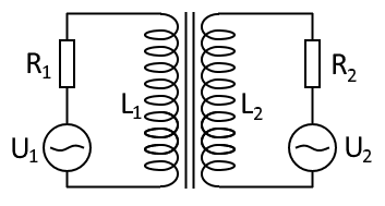
You can see the AC voltage sources as generators (or together with the resistor as a "consumer", if the amplitude is 0).
What I need to figure out are the Voltages across the inductors L1 and L2 and the currents which flow through the resistors R1 and R2. So the only things given are U1(t), R1, L1, U2(t), R2 and L2. What I already know is that the voltage across resistor R1 is:
[tex]U_{R1} = U_{L1} - U_1[/tex]
the same thing goes for the voltage across R2:
[tex]U_{R2}=U_{L2}-U_2[/tex]
Through some research I also found that the voltage across an inductor is given by:
[tex]U_{L1}=L_1 \cdot \frac{dI_1}{dt}+ M \cdot \frac{dI_2}{dt}[/tex]
From that we can conclude that:
[tex]U_{R1}=L_1 \cdot \frac{dI_1}{dt} + M \cdot \frac{dI_2}{dt} - U_1[/tex]
which is equavilent to:
[tex]I_1 = \frac{L_1}{R_1} \cdot \frac{dI_1}{dt} + \frac{M}{R_1} \cdot \frac{dI_2}{dt} - \frac{U_1}{R_1}[/tex]
and for the other side:
[tex]I_2 = \frac{L_2}{R_2} \cdot \frac{dI_2}{dt} + \frac{M}{R_2} \cdot \frac{dI_1}{dt} - \frac{U_2}{R_2}[/tex]
Where [tex]M = \sqrt{L_1 \cdot L_2}[/tex] is the mutual inductance.
The problem is, that this differential equation seems to be highly unstable in a simulation (using numerical differentiation). Is there any solution to that? Just having one side without the other, so setting [tex]M=0[/tex] works just fine, but with both sides everything just "explodes".
Hopefully someone can help me :D
You can see the AC voltage sources as generators (or together with the resistor as a "consumer", if the amplitude is 0).
What I need to figure out are the Voltages across the inductors L1 and L2 and the currents which flow through the resistors R1 and R2. So the only things given are U1(t), R1, L1, U2(t), R2 and L2. What I already know is that the voltage across resistor R1 is:
[tex]U_{R1} = U_{L1} - U_1[/tex]
the same thing goes for the voltage across R2:
[tex]U_{R2}=U_{L2}-U_2[/tex]
Through some research I also found that the voltage across an inductor is given by:
[tex]U_{L1}=L_1 \cdot \frac{dI_1}{dt}+ M \cdot \frac{dI_2}{dt}[/tex]
From that we can conclude that:
[tex]U_{R1}=L_1 \cdot \frac{dI_1}{dt} + M \cdot \frac{dI_2}{dt} - U_1[/tex]
which is equavilent to:
[tex]I_1 = \frac{L_1}{R_1} \cdot \frac{dI_1}{dt} + \frac{M}{R_1} \cdot \frac{dI_2}{dt} - \frac{U_1}{R_1}[/tex]
and for the other side:
[tex]I_2 = \frac{L_2}{R_2} \cdot \frac{dI_2}{dt} + \frac{M}{R_2} \cdot \frac{dI_1}{dt} - \frac{U_2}{R_2}[/tex]
Where [tex]M = \sqrt{L_1 \cdot L_2}[/tex] is the mutual inductance.
The problem is, that this differential equation seems to be highly unstable in a simulation (using numerical differentiation). Is there any solution to that? Just having one side without the other, so setting [tex]M=0[/tex] works just fine, but with both sides everything just "explodes".
Hopefully someone can help me :D
Attachments

Last edited by a moderator: