
Intro to AC Power Analysis: Learn System Basics
Click for Series List
Part 1: The Basics
Part 2: Network Analysis
Part 3: Cyber Resilience
Instantaneous Power
The formula for power is: ##P=V\cdot I## , power= voltage*current. We call that, instantaneous power. Even when ##V## and ##I## are changing in time, ##P=V\cdot I## applies for each instant. It matters not if the ##V## or ##I## changes are `sinusoidal, what their frequency is, or even if they are aperiodic. ##P=V\cdot I## is something you can use always. There are no exceptions that I can think of.
You don’t need Ohm’s Law to use ##V\cdot I##, because ##V## refers to the voltage at one point relative to the ground, and ##I## refers to the current flowing past that point. But suppose you have a resistor ##R##, and you want to calculate the power dissipated by it. Using Ohm’s Law, the voltage drop across ##R## is ##V=I\cdot R##. In this case, V is the voltage drop between two points in a circuit. The power dissipated is ##(V)\cdot I=(I\cdot R)\cdot I = I^2\cdot R## . If you have a capacitance ##C## instead of ##R##, then you need to use the differential equation ##I=C\frac{dV}{dt}## If you have an inductance ##L##, then you need to use the differential equation ##V=L\frac{dI}{dt}## .
Table of Contents
Sinusoidal Power
Let’s jump directly to sinusoidal waveforms such as we have in AC circuits. Let ##V## and ##I## be sinusoids of the form ##\cos{(\omega t+\phi)}##. What happens to the instantaneous power? Well, ##P=V\cdot I## still applies, but now ##P## varies with time, and how it varies depends on the phase angle of ##V## relative to the phase angle of ##I##. If the relative phase is zero, we say that voltage and current are “in phase”. That is depicted below.
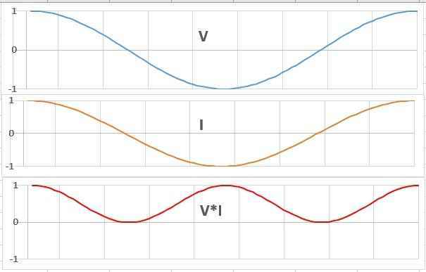
Note that the frequency of ##V\cdot I## is twice the frequency of ##V## or ##I##, and that the value of ##V\cdot I## is zero twice in the cycle, and that the average of ##V\cdot I## is not zero.
Sidebar: Students often fail to understand the AC behavior of ##V\cdot I##, especially if they have been taught to think of the water in a pipe analogy, or if they attempt to understand electricity as transport of electrons. Those students may think that if current flows back and forth, that power must do the same. They forget that in this case, when ##V## is minus, ##I##is also minus, therefore ##V\cdot I## is plus. The power flow is a plus for the entire cycle. The water analogy does not work for AC.
Suppose ##V## and ##I## are not in phase? In this picture, I shifted ##I## (dotted line) by an angle 90 degrees relative to ##V## (blue). ##V\cdot I## is shown as red-green shaded areas; red  means power flowing right (+) and green means minus power flowing left (-). Note that the areas of red and green are equal in this case, so they cancel. Power flows just as much to the left as to the right, so the net energy over the entire cycle is zero. What should we call this peculiar state? Referring to the entire cycle, we call it pure imaginary power (also called reactive power, also called VARs). Don’t be fooled, even in this case instantaneous ##V\cdot I## remains real.
 Here, ##I## is shifted only 45 degrees relative to ##V##. We see that ##V\cdot I## is predominantly red, but still partially green.
We can now generalize to all possible phase shifts. We discuss averages for the entire cycle.
- Phase 0 is pure real power, phase 180 is pure real power flowing in the opposite direction.
- Phase 90 is pure imaginary power, phase 270 is pure imaginary power flowing in the opposite direction.
- Any other phase is a linear combination of nonzero real power and nonzero imaginary power
Sidebar: Power is frequently confused with energy. Power is the rate of delivery of energy. One kWh of electric energy may cost $0.15 on your invoice. It could be delivered as 1 kW for one hour, or 10 kW for 6 minutes, or 0.1 kW for 10 hours.
The press very often gets it wrong, saying things like “this plant supplies enough power for 1000 homes per year.” Be on the alert for that. Power plants and power lines are rated by their ability to deliver power, not energy. Batteries, on the other hand, are rated by their energy storage. For example, a AA battery’s label may say 2000 milliamp-hours. Assuming a constant 1.5 volts, it stores 2000*1.5 or 3000 milliwatt-hours of energy.
Complex Power
In 1893, my hero Charles Proteus Steinmetz published a pape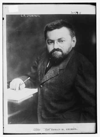 r that explained the great advantages of complex AC analysis. The other electrical geniuses of the day (including Nikola Tesla) were all using tedious integral calculus and expressions using definite integrals of ##\cos{(\omega t+\phi)}##, or the Euler form ##e^{-j\omega t+\phi}##. Steinmetz left them in his dust because he recognized the combination of fortuitous luck with coincidences of mathematics that were relatively obscure at the time. Namely:
- Manufacturers were already making AC generators in 1893 that generated sinusoidal voltages.
- The sinusoid is the only mathematical function that has the property that differentiation and integration return a function of the same form but shifted 90 degrees.
Steinmetz found that by restricting his equations to an integer number of whole cycles, and by replacing real quantities with complex ones, we obtain quasi-static equations that are hugely simplified relative to integral calculus. Simpler how?
- DC ##P=V\cdot I## becomes AC ##\bar S=\bar V\cdot \bar I##where ##\bar S## is complex power, usually written as ##\bar S=P+jQ## where ##P## is real power and ##Q## is imaginary power. (Actually, it should be ##\bar S=\bar V\cdot \bar I^*## but, I’m ignoring the sign of Q.)
- DC Ohm’s Law ##V=I\cdot R## becomes AC ##\bar V=\bar I\cdot \bar Z## where ##\bar Z## is the complex impedance. ##\bar Z## includes resistance, inductance, and capacitance.
- Differential equation terms in DC (like ##C\frac{dV}{dt}## and ##L\frac{dI}{dt}## ) become algebraic in AC.
- Series, parallel, Kirchhoff’s Laws, mesh analysis, matrix analysis: essentially all the tools and methods of DC circuit analysis become directly applicable to AC if we just use complex and whole cycles.
If you are unfamiliar with complex numbers, I recommend my Insights Article and this tutorial.
Sidebar: I am baffled that 123 years after Steinmetz, tedious methods are still being taught to students, including ), and forms. I see no educational value in that. Students can learn the instantaneous form, and then jump directly to the complex form without learning any of the intermediate forms that expressly use.
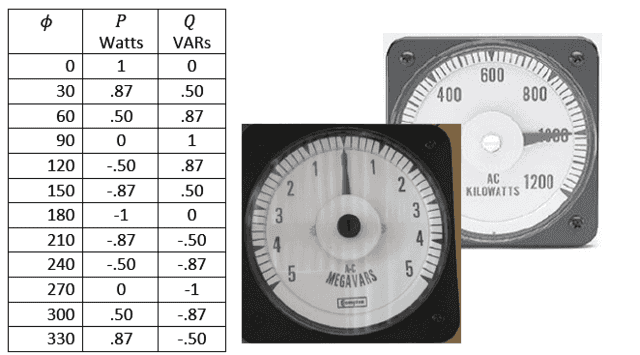
Next, think once again of the pictures from above with the red-green areas depicting V*I. Instead of time-varying instantaneous V*I, we will focus on just the whole cycle averages, P (as measured by an AC Wattmeter) and Q (as measured by an AC VARs meter). P and Q will be constant in time, but they will vary as we change the phase shift. The meter readings versus ##\phi## are shown in the table.
Mysterious Q
Q is the object of much mystery to many people. In college, I remember joking between the E.E. and M.E. students. The E.E. said, “I’ll explain imaginary power if you explain entropy.” A recent PF thread expended 76 posts attempting to clarify Q with little success. In part 2 of this Insights, I’ll explain why is important to grid voltage control.
To review, ##P+jQ=\bar V\cdot \bar I## implicitly includes both the magnitude and phase information. Simply using complex math, we can express all possible phase shifts in a simple static expression. Also, note that the variable time does not appear in either the instantaneous form or the complex form. We call the complex AC expressions “static” because do not explicitly appear in them.
In real life, we also use the complex form to model transient evolutions in the power grid including time intervals smaller than one cycle. This would seem to contradict its definition as a static expression that expresses the average over an integer number of whole cycles. Notwithstanding the contradiction, complex transient calculations have been proven to be highly accurate when verified against measurements many times.
Are Power and VARs Conserved?
It is tempting to think that if we add up all the power produced and power consumed in a circuit, that the net must be zero. Ditto for VARs produced and consumed. It’s not that simple.
Energy is conserved. That is one of the fundaments of (non-GR) physics. Why not power also? It is time to be precise with the terms. We are discussing electric energy, not other forms of energy. Electric energy is lost as heat to the environment by the ##I^2 R## terms. Power plants convert other forms of energy to electric energy. Most loads convert electric energy to other forms of energy. So electric energy is not conserved in the grid, and therefore neither is power.
VARs are more interesting. There can never be a battery to store VARs. VARs cannot be converted to any other form. We know that because ##P=V\cdot I## has no VARs. Thus, it is a curiosity that VARs are conserved in AC circuits. VARs produced minus VARs consumed must sum to exactly zero. If you find a case where they do not sum to zero, you made an error.
So we have an apparent paradox. VARs seem to be only a mathematical artifact with no physical significance. VARs can’t be stored or converted. It sounds like they don’t exist. But in Part 2 of this series, we’ll learn how VARs play a central role in the control of voltage magnitudes in the grid.
—
PF members sophiecentaur, and Jim Hardy contributed to this article.
Dick Mills is a retired analytical power engineer. Power plant training simulators, power system analysis software, fault-tree analysis, nuclear fuel management, process optimization, power grid operations, and the integration of energy markets into operation software, were his fields. All those things were analytical. None of them were hands-on.
Dick has also been an exterminator, a fire fighter, an airplane and glider pilot, a carney, and an active toastmaster.
During the years 2005-2017. Dick lived and cruised full-time aboard the sailing vessel Tarwathie (see my avatar picture). That was very hands on. During that time, Dick became a student of Leonard Susskind and a physics buff. Dick’s blog (no longer active) is at dickandlibby.blogspot.com, there are more than 2700 articles on that blog relating the the cruising life.


Just found an interesting article about HVDC http://www.lead-central.com/AssetManager/02427e68-6f15-4f3a-9749-d37abf613741/Documents/ABBReview/ABB-1259-WPO_60_years_of_HVDC.pdfgood introduction for those of us who never worked with itlooks like it's coming our way
Thanks for sharing your knowledge
That’s amazing. It does look like fun, thanks for sharing Jony130.
The surge tank is there for C1, and inertia is there in the turbine’s flywheel.
Actually, my biggest objection to the water analogy is that based on the questions I see, some water analogy students never learn pressure*flow is power. They think the flow is power, and that electrons in a circuit are like little energy capsules that deliver discrete bits of energy to the destination. Even Jony130’s clever water circuit does not help anyone visualize power versus time, only water flow versus time.
The whole thing is exacerbated because teaching the water analogy is often 100% verbal, when pictures are really needed to clarify. Jony130’s is an example of a very clever circuit, but too difficult to explain without a picture.
Water analogy (just for fun)
[ATTACH=full]97999[/ATTACH]
As you can see Inductor water analogy is a turbine with a flywheel. The mass of the flywheel determines the value of a inductor inductance.
And the bipolar transistor water analogy
[ATTACH]98000[/ATTACH]
Glad you enjoyed it. Just yesterday, I saw it again in the press — “this wind farm makes up to 100 MW per year.”
“”The water analogy does not work for AC.”
It does work, but you have to switch the direction of water flow (I) and the direction of height difference (U) at the same time.”
Well yes, but you have to embellish the water analogy a lot. Reservoirs on each end instead of a hose with nozzle, something like surge tanks to analogize capacitors, and something like a fluid with intertia to analogize inductors.
“The water analogy does not work for AC.”
It does work, but you have to switch the direction of water flow (I) and the direction of height difference (U) at the same time.
“this plant supplies enough power for 1000 homes per year.”
Oh, I love it. So after 50 years it can power 50,000 homes.
“I am baffled that 123 years after Steinmetz, tedious methods are still being taught to students, [b]including ), and forms.[/b]”
Is there something missing? I’m not sure if students always know about complex numbers at the point where AC is introduced. I had some basic AC stuff in school, but no complex numbers as far as I remember (and even if we had them, then certainly later).
Thanks Jim, I’ll review that paragraph tomorrow. But you have to let go of “instantaneous VARS”. they don’t exist. The article says that more than once. VARs exist only in whole cycle averages.
I never could quite wrap my brain around AC power in school.
I got decent enough to be able to do the problems but never really had a good conceptual picture in my head.
Your first sidebar there addresses the root of my issue. I always understood DC circuits with the water in the pipe analogy.
In the end I took just enough Power classes to realize I didn’t want to be an power engineer :)
Thanks for sharing your knowledge
Those two minor adjustments make part 1 flow for me.
This paragraph confuses me" Next, think once again of the pictures from above with the red-green areas depicting V*I. Instead of time-varying instantaneous V*I, we will focus on just the whole cycle averages, P (as measured by an AC Watt meter) and Q (as measured by an AC VARs meter). P and Q will be constant in time, but they will vary as we change the phase shift . The meter readings versus ϕ are shown in the table."Perhaps this verbage would lead the mind more directly ?"Volts and amps will remain constant in amplitude but their phase will shift. So power P which is VIcostheta , and Q which is VIsintheta, will vary as we change the phase shift."?old jim "
I missed the definition of Left and Right as describing direction of VARS first few times through… My bad not yours. That hung me up…. i see you clearly stated it in thge text just above graphic…. Maybe a red and a green arrow on the graphic for dummies like me? Instantaneous vars must represent energy that goes somewhere. I think of them as stored alternately in capacitive or inductive components of the power system.Neither Inductance nor capacitance generates heat , so imaginary power is a good name for the energy hiding there . For those who think in equations,observe Power = VI if both V and I are sines (as you established) sin^2(x) = 1/2 – 1/2 cos(2x)observe it gained both the DC offset and frequency doubling shown in your graphic.Which i really like.
One reason for using other approaches is that the complex (phasor) math is the result of the general wave equation when the frequency is held constant. While that's true for typical power applications and can be stretched for harmonics analysis, it is less true for communications theory where frequencies can vary a lot. When one tries phasors on some such problems aliasing errors abound. Still, this insight is about power, and phasor math is great for power analysis.