What are the key considerations for designing an Inductrack highway system?

AI Thread Summary
Key considerations for designing an Inductrack highway system include the structure and dimensions of magnetic rings for levitation, the design of passive levitation rails, and the compatibility of the system with various vehicles. The levitation aims to enhance efficiency, safety, and speed by reducing road-tyre drag, with energy sourced from inductive loading of laminated conductors interacting with vehicle magnets. Feasibility concerns arise regarding energy consumption, particularly in overcoming air resistance, which is significant in vehicle transportation. The project requires a theoretical prototype to analyze economic measures and material costs effectively. Overall, the discussion emphasizes the need for detailed calculations and designs to assess the project's viability.
marko1
Messages
7
Reaction score
1
Thread moved from the technical forums to the schoolwork forums
Summary:: I have to show to my university class an innovative feasible project. It's about new generation Highways, based on the Inductrack model. There are a lot of questions that I have to ask to know if it's a feasible project, so if there is someone patient that have time to answer all my questions and help me solve my issues I'll be very grateful.

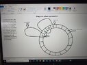
The idea is to insert in each wheel of a car two rings of permanent magnets, that will allow to levitate the vehicle on a flat track made of thin aluminum sheets covered with a pattern of laminated conductor strings shorted at their end that forms a close packed array.
My primary issues are these:
-Best structure of magnetic rings/magnets itself (dimensions, type of magnets, magnetic strength ecc.)
-Possible structure of rails with closed packed arrays for passive levitation ( how the vehicle reach stability, rail material (aluminium?), arrays structure, dimensions ecc.)
-Compatibility for most vehicles
-Feasibility study of magnetic rails splitter
-Propulsion system using magnets/electromagnets on the rail
-Brake
-Energy consume of the system for each vehicle on different speed
-Efficency of the system, L/D ratio
 
Last edited:
Physics news on Phys.org
Welcome to PF. :smile:

We need a bit more from you in order to try to offer our thoughts:

** What is the purpose of the levitation? How does that help anything?

** Where does the energy for the levitation come from?

** What reading have you been doing about magnetic levitation so far? Can you post a couple links please to that reading? Thanks.

:smile:
 
Thank you. So the purpose of the levitation is to convert existing highways into more efficient, eco-friendly, safe, and fast roads. A client will drive the car until it starts floating at low speed, then the user will be able to turn off the engine: a software will drive each car to the destination. Levitation is useful for the road-tyres drag. The main energy loss is needed to battle the air resistance, but I'm non considering tunnels because there have to be used special vehicles. The energy of the levitation come from a inductive loading of the flat pattern of laminated copper or aluminium strings shorted at their end that interact with the permanent magnets fixed on the vehicle. When the vehicle is moving, it levitates passively. I shared the main link that helped me with my hypothesis, I also searched few other pdf's and similar explanations.
 

Attachments

Here is one place to start your study.

https://en.wikipedia.org/wiki/Electrodynamic_suspension

Remember, when using Wikipedia, the most useful information is given in the documents linked under References at the bottom of the page.

I'm skeptical that the project requirements are really to calculate those things you list. It would take a team of engineers many years to design such a system. Can you post the exact statement of the project requirements? Also your field of study and for how many years you have been studying it.
 
  • Like
Likes berkeman
anorlunda said:
Here is one place to start your study.

https://en.wikipedia.org/wiki/Electrodynamic_suspension

Remember, when using Wikipedia, the most useful information is given in the documents linked under References at the bottom of the page.

I'm skeptical that the project requirements are really to calculate those things you list. It would take a team of engineers many years to design such a system. Can you post the exact statement of the project requirements? Also your field of study and for how many years you have been studying it.
Thank you for the answer and sorry for my bad explanation. I am studying economics in Italy, 3rd grade, and my requirement is to explain economic measures and analysis of an imaginary but feasible innovative project. I am very interested in the physics and mechanic feasibility of the project because after that I will be able to consider some values such expenses for materials, magnets, energy...
My goal is to have a quite accurate theoretical prototype of the system so I can go to the next step and do the financial and economics analysis.
 
marko1 said:
and my requirement is to explain economic measures and analysis of an imaginary but feasible innovative project.
That is problematic for me so far in reading your posts. "Feasible" means that others would have investigated it previously, and probably would have implemented it if it were indeed feasible.

Can you think of some reasons why your project proposal may not be feasable? Remember that there is no free energy, and the energy loss from air resistance is very significant in vehicle transportation.
 
berkeman said:
That is problematic for me so far in reading your posts. "Feasible" means that others would have investigated it previously, and probably would have implemented it if it were indeed feasible.

Can you think of some reasons why your project proposal may not be feasable? Remember that there is no free energy, and the energy loss from air resistance is very significant in vehicle transportation.
Thank you for the answer. Honestly I don't see why it may not be feasible: in the pdf that I've linked they calculate also the energy expenses and they come up with these results: at 500km/h a 40000 kg train need 8MW of power to overcome air resistance, and 4% of that for levitate( approximate because is unknown the design), so if we take into consideration a car that weights 2000kg I think the energy loss is affordable. I want to underline that I'm an economics student so I follow what other teams and students have already calculated.
If you want to understand better my idea I've partially followed the linked pdf. Thank you.
 
Well to your credit, your reference it to LLNL, which is a verey credible organization. It would help if you could post some of your initial diagrams for how you envision this working. I'm still having trouble understanding how this would work (I only read the LLNL abstract), so the more diagrams the better. Thanks.
 
berkeman said:
Well to your credit, your reference it to LLNL, which is a verey credible organization. It would help if you could post some of your initial diagrams for how you envision this working. I'm still having trouble understanding how this would work (I only read the LLNL abstract), so the more diagrams the better. Thanks.
Sure, I am glad to share it with you. I'll do it in few hours because here is early morning. I'll send you my drafts and a better explanation of how has to work. Hear you soon.
 
  • Like
Likes berkeman
  • #10
berkeman said:
Well to your credit, your reference it to LLNL, which is a verey credible organization. It would help if you could post some of your initial diagrams for how you envision this working. I'm still having trouble understanding how this would work (I only read the LLNL abstract), so the more diagrams the better. Thanks.
Yesterday I sent you the wrong pdf. I've also considered that one, but this one that I'm sending you now allows you to understand better my idea. I also send 2 photos with a very basic explanation of the idea.
 

Attachments

  • Inductrack.pdf
    Inductrack.pdf
    150.1 KB · Views: 146
  • 16514184952638342193267070731641.jpg
    16514184952638342193267070731641.jpg
    27.9 KB · Views: 107
  • 16514185198491458973305662863642.jpg
    16514185198491458973305662863642.jpg
    53.4 KB · Views: 130
  • #11
marko1 said:
Yesterday I sent you the wrong pdf. I've also considered that one, but this one that I'm sending you now allows you to understand better my idea. I also send 2 photos with a very basic explanation of the idea.
I've posted this thread because I'd like to know ideal magnets dimensions according to the design shown in the photo following to calculations that have been already made for another similar system shown into the linked pdf. Let's say an approximate weight of 2000 kg with a medium aerodynamics value. What changes is that there is the tire's tear between magnets and track.
Also referring to the linked pdf, I'd like to know which are track's best width and thickness, and the possible distance between each conductor wire. Thank you for your time.
 
Back
Top